4010ES OPERATING INSTRUCTIONS
FOLLOWING AN ALARM, SUPERVISORY, OR TROUBLE CONDITION
YOUR SAFETY AND THE SAFETY OF THOSE AROUND YOU ALWAYS COMES FIRST.
Actions taken during a fire depend upon local practices. Be sure you know what to do.
Systems Using Global Acknowledge
ALARM
RED LED FLASHES AND TONE ALERT PULSES
SUPERVISORY/TROUBLE
YELLOW LED FLASHES AND TONE ALERT ON STEADY
Acknowledging Alarms
1. Unlock and open the panel door. The appearance of the alphanumeric
display depends on whether the Display 1
st
Alarm Option is enabled or
not.
• If Display 1
st
Alarm Option is enabled. The display alternates
between two screens similar to Screen 1 and Screen 2 below.
• If Display 1
st
Alarm Option is not enabled. Only a screen similar to
Screen 1 appears, indicating the total number of alarm conditions
present on the system.
2. Press the <FIRE ALARM ACK> key under the flashing red LED. Read
and follow the instructions on the alphanumeric display. The tone-alert
silences and the ALARMS LED changes from flashing to ON steady.
Silencing the Signals
Press the ALARM SILENCE key and read the display. The alphanumeric
display reads “ALARM SILENCE IN PROGRESS” and the ALARM
SILENCED LED turns on steady.
Resetting the System With Active Alarms
1. Press the SYSTEM RESET key. The alphanumeric display reads
“SYSTEM RESET IN PROGRESS”.
2. If all zones or devices in alarm reset, the ALARMS LEDs flash. Press the
FIRE ALARM ACK or the PRIORITY 2 ACK key, or both. The message
“SYSTEM IS NORMAL” appears.
3. If a zone or device remains in alarm and fails to reset, the message
“ALARM PRESENT, SYSTEM RESET ABORTED” appears.
4. Read the display to determine the type and the location of the device(s)
in alarm. Follow local procedures to investigate the area of the building
in alarm. Look for devices in the alarm state, for example, pull stations
with the handle down, or smoke detectors with the LED lit.
Performing a Hardware Reset
To perform a hardware reset, press the SYSTEM RESET key when no
alarms are present.
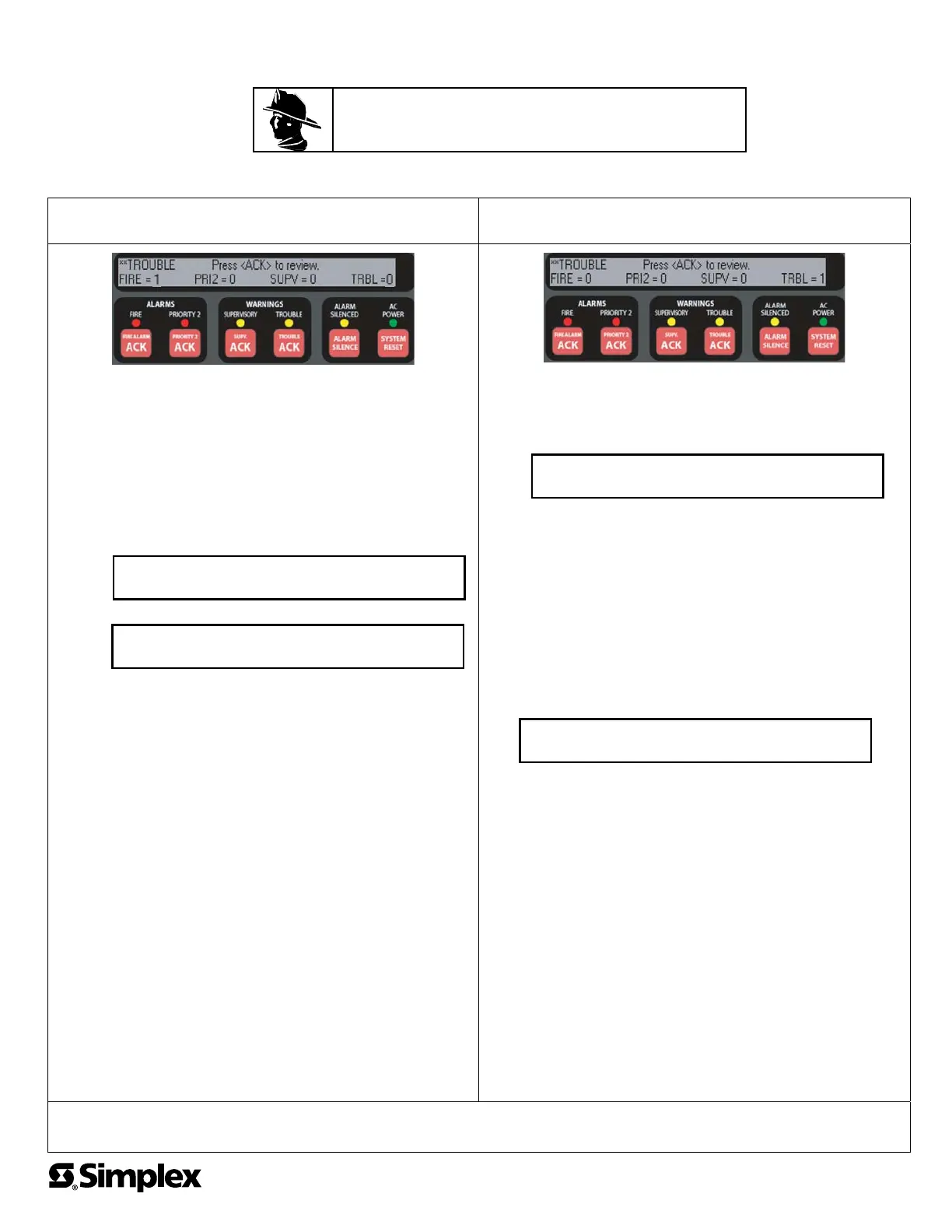
Acknowledging Supervisory or Trouble Conditions
1. Unlock and open the panel door. The alphanumeric display shows the
number of abnormal conditions. (This example describes managing a
Trouble condition. A Supervisory condition is handled similarly.
2. Press the <TROUBLE ACK> key under the flashing yellow LED. The
display shows the area and type of problem. The tone alert silences and
the yellow LED turns on steady.
3. Read the alphanumeric display to determine the cause of the trouble.
4. If a Trouble condition exists, restore or replace the defective equipment
(switch, wire, device, etc.) in accordance with the equipment’s
instructions.
The Trouble condition automatically clears when the problem has been
corrected.
After a short delay, the system returns to normal and displays the
following.
If the Trouble Does Not Clear
1. If the trouble is a Style D initiating device circuit trouble, a City Circuit
trouble, or a 24 Point I/O trouble, press the SYSTEM RESET key.
2. If the trouble does not clear or toggles and reappears, you may choose
to disconnect the device or disable the point.
Note: A disabled point does not report alarm conditions or other status
changes. Appropriate steps must be taken to provide alternate means of
protecting the area covered by the disabled point. Repair or replace the
failed device or circuit as soon as possible and reenable the point.
In case of trouble, notify:
Name: _______________________________________________
Address _______________________________________________
Phone # _______________________________________________
FRAME AND MOUNT THESE INSTRUCTIONS ADJACENT TO THE PANEL.
SEE OPERATOR’S MANUAL FOR DETAILED OPERATION.
**FIRE** Press (ACK) to review.
FIRE = 1 PRI2=0 SUPV=0 TRBL=0
FIRST FLOOR EAST WING ROOM 31
PULL STATION
Screen 1
Screen 2
**TROUBLE** Press (ACK) to review.
FIRE = 0 PRI2=0 SUPV=0 TRBL=1
SYSTEM IS NORMAL
9:27:40 FRI 15 SEP 00
© 2011 SimplexGrinnell LP. All rights reserved. 579-995 Rev. A
 Loading...


