2-14
FigureTag FD4-709-07
+
-
+
-
BACKUP 2
PRIMARY 1
LISTED
SIMPLEX
FIRE ALARM
CONTROL
PANEL
2120,
2
1
3
4
SEE NOTE 2
SEE NOTE 2
SEE NOTE 3
SEE
NOTE
3
EOL
RESISTOR
(IF USED)
BLK
BLK
RED BROWN
WHITE
2
1
3
4
BLK
RED BROWN
WHITE
4098-9830
REMOTE LED
(SEE
NOTE 1)
4098-9684
HEAT DETECTOR
BASE
BLK
4098-9684
HEAT DETECTOR
BASE
INITIATING
CIRCUIT
4098-9830
REMOTE LED
(SEE
NOTE 1)
4001, 4002
4020, 4100+, 4100U
4004, 4005 OR 4006
4100ES ,
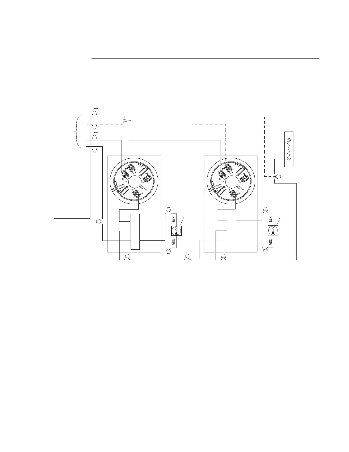
Figure 2-6. 4098-9684 Heat Detector LED Base Connections for Style B or D Initiating Circuits
Notes:
1. If used, 4098-9830 remote LED is polarized; observe color-coded wiring.
2. It is recommended that the Primary-1 and the Backup-2 lines be in separate wire runs and in
compliance with local requirements.
3. For Style D initiating circuit, wire per dotted lines and do not use EOL resistor. If Style B
initiating circuit, refer to wiring diagrams provided with the system panel for proper EOL
resistor value.
4098 Bases,
Continued
Wiring
 Loading...


