Power Wiring (AC and Battery)
Overview
The amplifier is powered through the Power Distribution Module (PDM). The PDM takes power directly from a dedicated AC line and the two backup
batteries, and distributes power to each bay in the cabinet.
Power Distribution Module Connections
The Power Distribution Module (PDM) connects to every power supply and 100 W amplifier in each back box.
Connect the 734-012 Harness (734-013 for 220/230/240 VAC versions) from the top connector on the PDM to the 100 W amplifier.
1. Wire 120/220/230/240 VAC to the PDM, keeping AC wires at least 1 inch (25 mm) away from all other wires. AC power must be kept to the right
side of the cabinet, in the non-power-limited area.
2. Connect batteries to P5 on the PDM using Harness 734-015.
3. Connect the PDM to the amplifier using Harness 734-012 (734-013 for 220/230/240VAC versions).
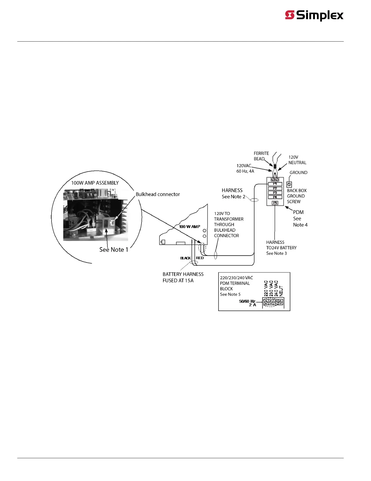
• Connect the separate red and black wires (with yellow female terminations) to the RED and BLACK plugs on the 100 W amplifier.
• Connect the white and black wires, which terminate together in a white snap-on connector, to the bulkhead connector at the bottom of the
amplifier assembly, as shown Figure 4.
Figure 4: PDM Connections
Note:
1. Second bulkhead connector here in 220/230/240VAC versions.
2. The harness is 734-012 or 734-013.
3. The harness is 733-015.
4. 566-246 or 566-248 (see note 5).
5. This is the 566-248.
page 6 579-174 Rev. Q
Digital/Analog Amplifiers Installation Instructions