EasyManuals Logo

Simplex 4100U Installation Instructions

Simplex 4100U
6 pages
To Next Page IconTo Next Page
To Previous Page IconTo Previous Page
Page #4 background imageLoading...
Page #4 background image
4
Remote annunciators are made up of several modules, and each module has its own set of
installation instructions. The figures below and on the next page show the general setup for each
remote annunciator. Refer to the appropriate manuals to install specific modules. Manuals are
found in the ship group for each module.
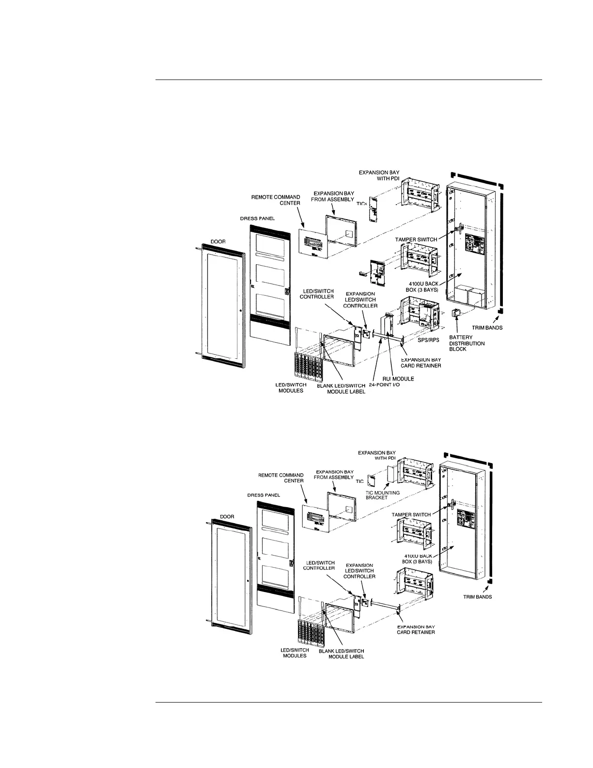
As shown in the figures, expansion bays with the power distribution interface (PDI) are always
used in the remote annunciator. (CPU bays are never used.)
Figure 1. 4100-9607, -9608, -9609, & -9610 Remote Annunciator Installation
(4100-9610 Shown)
Figure 2. 4100-9611, - 9612, -9613, & -9614 Basic Remote Annunciator Installation
(4100-9611 Shown)
Note: The Remote Command Center is an option with 4100-9610 and 4100-9611.
Continued on next page
Remote Annunciator Installation, (continued)
General Setup

Other manuals for Simplex 4100U

Questions and Answers:

Question and Answer IconNeed help?

Do you have a question about the Simplex 4100U and is the answer not in the manual?

Simplex 4100U Specifications

General IconGeneral
Control Panel TypeAddressable Fire Alarm Control Panel
DisplayLCD
Power Supply120/240 VAC, 50/60 Hz
Max Signaling Line Circuits (SLC)2
Operating Temperature0°C to 49°C (32°F to 120°F)
Humidity Range10% to 93% non-condensing
Network CapabilityYes
Communication ProtocolRS-232, RS-485
Battery Backup24 VDC
NAC Outputs4
Signaling Line Circuits (SLCs)2
Power Supply Current3.0 A
Max Notification Appliance Circuits (NAC)4
Max Releasing Circuits4
Max Relay Circuits4
Communication PortsRS-232, RS-485

Related product manuals