5. (4903 AN only)
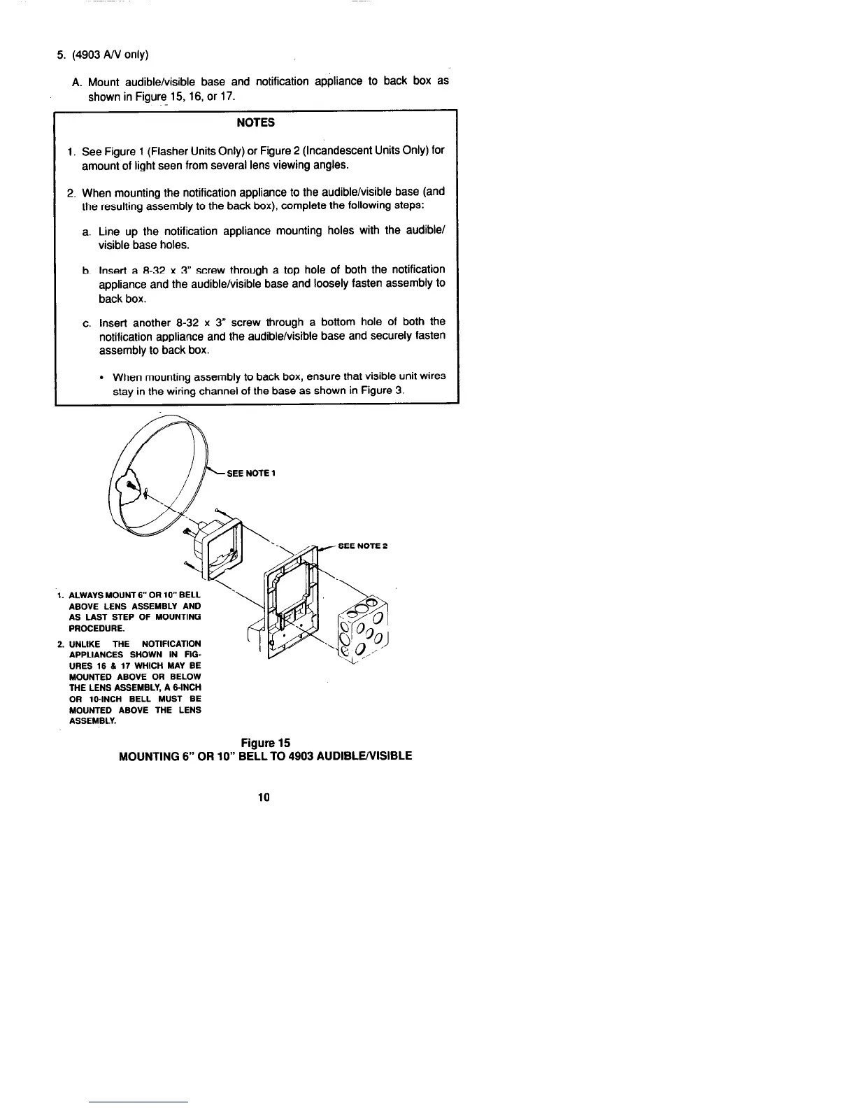
A. Mount audible/visible base and notification appliance to back box as
shown in Figure 15, 16, or 17.
NOTES
1. See Figure 1 (Flasher Units Only) or Figure 2 (Incandescent Units Only) for
amount of light seen from several lens viewing angles.
2. When mounting the notification appliance to the audible/visible base (and
the resulting assembly to the back box), complete the following steps:
a. Line up the notification appliance mounting holes with the audible/
visible base holes.
b. Insert a 8-32 x 3” screw through a top hole of both the notification
appliance and the audible/visible base and loosely fasten assembly to
back box.
c. Insert another 8-32 x 3” screw through a bottom hole of both the
notification appliance and the audible/visible base and securely fasten
assembly to back box.
l
When mounting assembly to back box, ensure that visible unit wires
stay in the wiring channel of the base as shown in Figure 3.
SEE NOTE 1
1. ALWAYS MOUNT6” OR lo” BELL
‘.
ABOVE LENS ASSEMBLY AND
AS LAST STEP OF MOUNTING
PROCEDURE.
2. UNLIKE THE NOTIFICATION
APPLIANCES SHOWN IN FIG-
URES 16 (L 17 WHICH MAY BE
MOUNTED ABOVE OR BELOW
THE LENS ASSEMBLY, A CINCH
OR IO-INCH BELL MUST BE
MOUNTED ABOVE THE LENS
ASSEMBLY.
Figure 15
MOUNTING 6” OR 10” BELL TO 4903 AUDIBLE/VISIBLE
10