4
Setting the Ceiling-Mount A/V Address
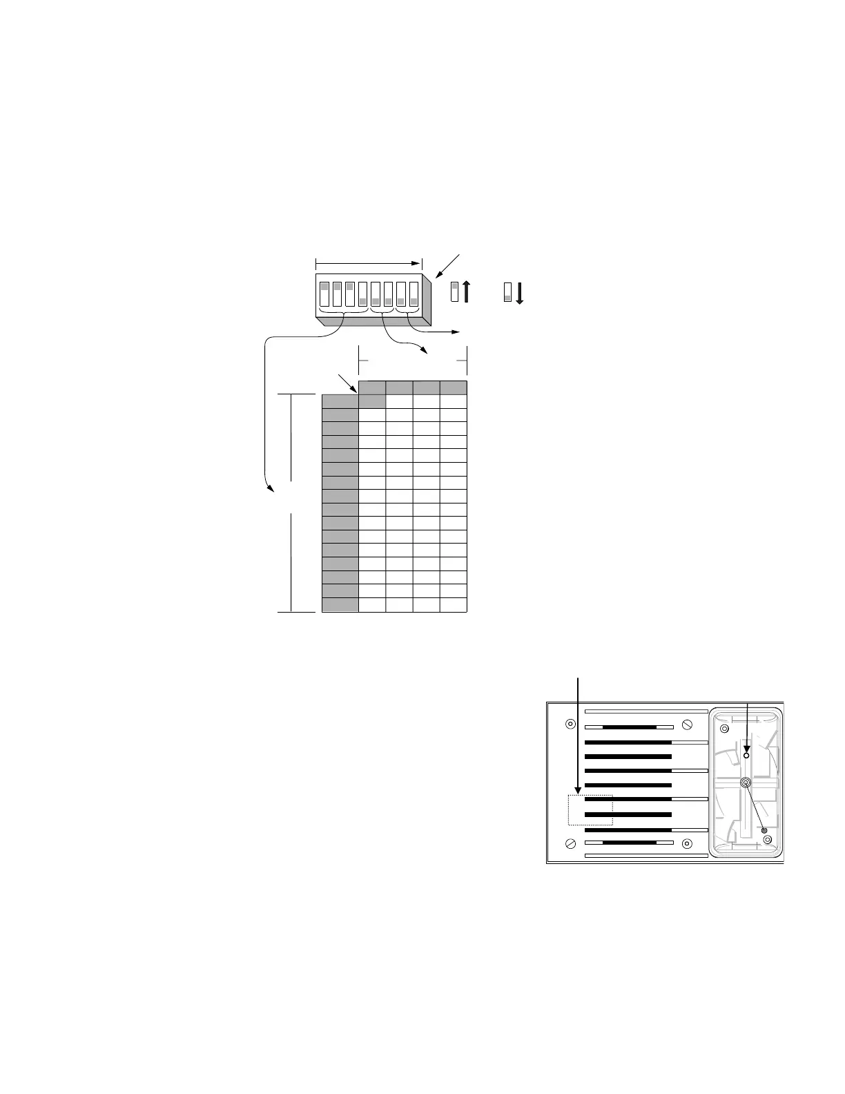
Each TrueAlert notification appliance has a unique address. Each appliance’s address is set via an eight-position DIP
switch, as shown in Table 2 (see Figure 3 for the general DIP switch location). DIP switch position 1 is the least
significant bit (LSB) and position 8 is the most significant bit (MSB).
Note: DIP Switches 1 through 6 are used to set the possible 63 address codes. DIP Switches 7 and 8 are not used and
are set to “OFF.”
Use a small screwdriver or pen to set the switches, and then record the address. This information provides an aid in
troubleshooting the system.
Table 2. TrueAlert Ceiling-Mount A/V Units – DIP Switch Address Chart
0000 1000 0100 1100
0000
0 163248
1000
1 173349
0100
2 183450
1100
3 193551
0010
4 203652
1010
5 213753
0110
6 223854
1110
7 233955
0001
8 244056
1001
9 254157
0101
10 26 42 58
1101
11 27 43 59
0011
12 28 44 60
1011
13 29 45 61
0111
14 30 46 62
15 31 47 63
LSB
MSB
1 2345678
1111
DIP SWITCHES 5 AND 6
DIP
SWITCHES
1 THRU 4
RESERVED FOR
FUTURE USE
NOT USED
ON
OFF
1 = ON 0 = OFF
DIP SWITCH SHOWN IS
SET AT ADDRESS 7.
Ceiling-Mount A/V Magnetic Test
Note: The TrueAlert Addressable Controller must be configured to support the
Ceiling-Mount A/V diagnostic testing.
Position magnet tester 553-810 to the bottom right side of the A/V cover near
the LED indicator (see Figure 4). Hold the magnet tester in place for a
minimum of two seconds or until the LED begins flashing.
In response to the magnetic test, the A/V LED emits one long flash denoting the
test acknowledge signal, and then another long flash denoting the first digit
(always zero) of the appliance address. The LED then flashes one to six times to
denote the second digit of the address, pauses, and then flashes one to nine times
to indicate the third digit of the address. One long flash always indicates a zero.
After the A/V LED flashes its address, the A/V goes into alarm (real appliance
test) or the LED illuminates (silent appliance test) for 2 to 3 seconds.
Important: Refer to the TrueAlert Addressable Controller Installation
Guide(574-762) for detailed information on appliance
diagnostic testing.
Figure 4. Appliance Magnet Test
MAGNET
TESTER
LOCATION
A/V LED