Class B NAC wiring table
Table 3 lists the maximum distances from the XPS to the last appliance in a Class B configuration, depending on wire gauge and current. Use Table 3 to
calculate wire distances for your application if you are using Class B wiring.
Table 3: Class B wiring distances
Alarm current @ 24 V
Max. distance w/ 18
AWG (0.8231 mm²)
Max. distance w/ 16
AWG (1.309 mm²)
Max. distance w/ 14
AWG (2.081 mm²)
Max. distance w/ 12 AWG
(3.309 mm²)
DC resistance
0.25 A 840 ft (256 m) 1,335 ft (407 m) 2,126 ft (648 m) 3,382 ft (1,031 m) 12 ohm
0.50 A 420 ft (128 m) 667 ft (203 m) 1,063 ft (324 m) 1,691 ft (515 m) 6 ohm
0.75 A 280 ft (85 m) 445 ft (136 m) 709 ft (216 m) 1,127 ft (344 m) 4 ohm
1 A 210 ft (64 m) 334 ft (102 m) 532 ft (162 m) 845 ft (258 m) 3 ohm
1.25 A 168 ft (51 m) 267 ft (81 m) 425 ft (130 m) 676 ft (206 m) 2.4 ohm
1.50 A 140 ft (43 m) 222 ft (68 m) 354 ft (108 m) 564 ft (172 m) 2 ohm
1.75 A 120 ft (37 m) 191 ft (58 m) 304 ft (93 m) 483 ft (147 m) 1.71 ohm
2 A 105 ft (32 m) 167 ft (51 m) 266 ft (81 m) 423 ft (129 m) 1.5 ohm
2.25 A 93 ft (28 m) 148 ft (45 m) 236 ft (72 m) 376 ft (115 m) 1.33 ohm
2.50 A 84 ft (26 m) 133 ft (41 m) 213 ft (65 m) 338 ft (103 m) 1.2 ohm
2.75 A 76 ft (23 m) 121 ft (37 m) 193 ft (59 m) 307 ft (94 m) 1.09 ohm
3 A 70 ft (21 m) 111 ft (34 m) 177 ft (54 m) 282 ft (86 m) 1 ohm
Note:
• Max. distance = distance from XPS to last appliance.
• This table is calculated at 50°C (120°F). If you are installing in locations that could be exposed to higher temperatures, refer to NEC Table 8.
• Distances are based on a 3 V drop, and take into account the worst-case panel output voltage.
• If CI wire is used instead of housing cable in a fire rated enclosure, reduce wiring distances by 38 ft (12 m) for every 10 ft (3 m) of potential
exposure.
Guidelines
• All wiring is 18 AWG (0.8231 mm²) (minimum) to 12 AWG (3.309 mm²) (maximum).
• All wiring is supervised and power-limited.
• The maximum alarm current is 3 A for each circuit. The supervisory current is 2.03 mA at 24 VDC.
• The nominal voltage rating is 24 VDC, 2 V p-p ripple (maximum).
• The total available current from the XPS is 9 A, unless it is used for REGULATED 24 VDC notification appliances, where the XPS is rated for 4
Amps notification current, and 1 Amp for other uses. Total available auxiliary power current is 5 A (1 Amp for REG 24), and rated at 2 A for each
circuit. Current used for card power by modules plugged into the PDI, as well as any auxiliary 24 VDC current, must be deducted from the total
9 A available current.
• All wiring that leaves the building requires over-voltage protection. Install module 2081-9044 (3 A) or 2081-9028 (1/4 A) inside a UL-Listed
electrical box wherever wire enters or exits the building. When using the 2081-9044, the maximum alarm current is reduced to 1/4 A for that
part of the circuit downstream of the module.
• Terminal designations + and - are for the alarm state.
• Compatible appliances for NACs are listed in Table 4.
• A maximum of 70 appliances can be supported for each circuit. If you are using 49CMT or 49CMTV series appliances, note that each of these
appliances counts as five units, therefore no more than 13 49CMT or 49CMTV series appliances may be placed on one circuit.
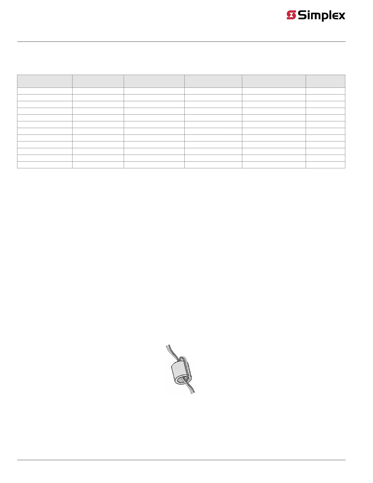
• For CE compliant systems, use the ferrite beads as shown in each figure. Loop wires once through the ferrite beads as shown in Figure 9.
4100-5129 includes three ferrite beads, order as needed.
Figure 9: Loop wires as shown.
• Auxiliary power only: In order to connect a circuit using power-limited wiring, the devices being powered must all be addressable, or a UL-
Listed EOL relay must be used to supervise the circuit. See Figure 10 for wiring directions for the EOL relay.
Note: The 2098-9739 Relay is used as an example. Other UL-Listed EOL relays can be used, depending on the application.
page 10 574-772 Rev. Q
XPS and XNAC Installation Instructions
 Loading...