Regent / 500 / 2500 / LT Series
1/2006 27 TP 300-4218-04-RG-SMAN
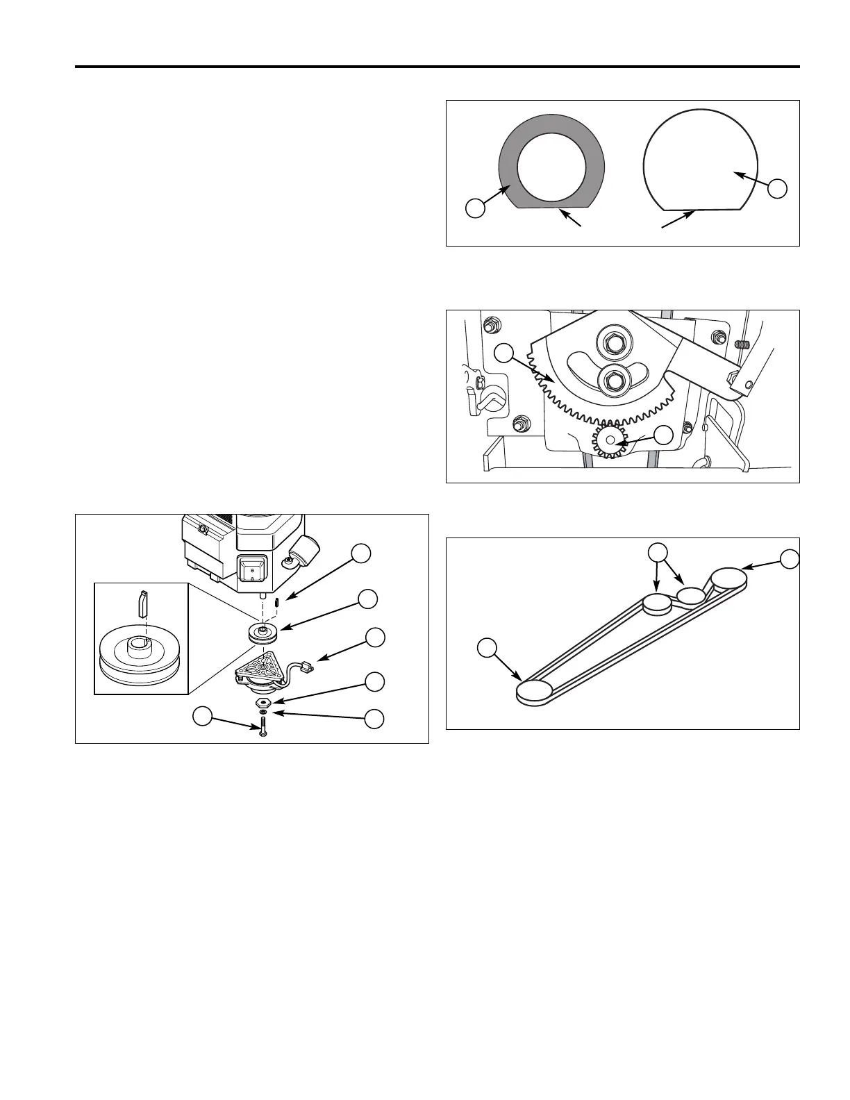
Figure 55. PTO Clutch Installation
A. Key D. Hex Washer
B. Engine Pulley E. Lock Washer
C. PTO Clutch Plug F. Capscrew
A
B
C
D
E
F
Figure 58. Drive Belt Routing
A. Engine Pulley C. Idler Pulleys
B. Transmission Pulley
A
B
C
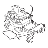
9. Align teeth on shaft (A, Figure 57) with teeth on gear
and push shaft up and hold in place.
10.Slide washer(s) (B, Figure 54) as required onto shaft
(D) and secure with clip (A).
11.Lower the front of the unit.
12.Turn the wheels straight.
13.Place the shaft cover (E, Figure 53) over steering
shaft (D) and secure by squeezing shaft cover (E)
base and placing into holes (G).
14.Apply a small mount of an anti-seize lubricant past
top the top of the steering shaft (D).
15.Install the steering wheel (F), and secure with washer
(C) and new nut (B). Torque nut to 180 - 240 in. lbs.
(20-27 Nm)
16.Release the parking brake. Check that the belt has
been routed correctly, See Figure 58, and that all
adjustable belt guides are adjusted to within 1/8”
(3.2mm) of the belt guide.
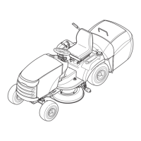
Figure 56. Top View of Washer and Tower Hole
A. Washer B. Tower Hole
A
B
Figure 57. Top View of Washer and Tower Hole
A. Sector Gear B. Steering Shaft
A
B
Flat Edges

 Loading...