ZT4000 - 44” & 48” Mower Deck
9
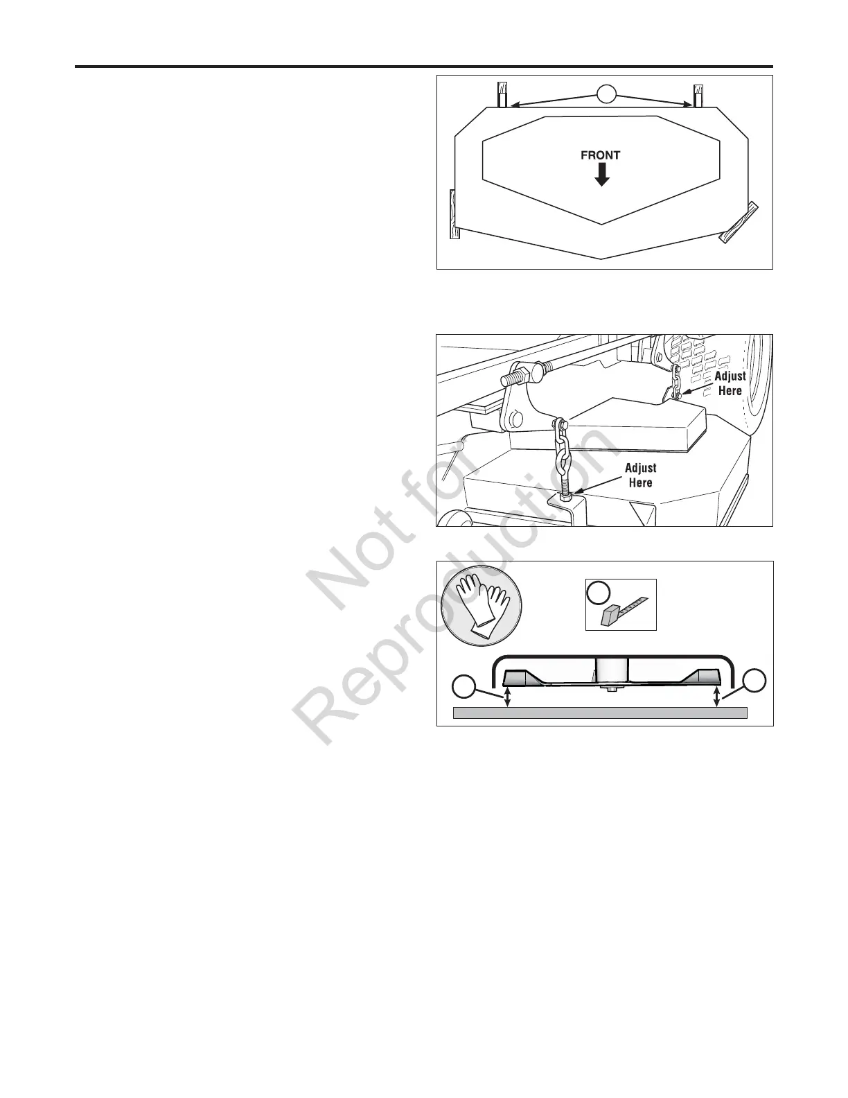
Figure 17. Hanger Chain Adjustment
Figure 16. 2 x 4 Locations
A. 1/4” Spacers
A
44” Models (S/N: All): 48” Models (S/N: 2014720668 &
Below):
6. Refer to Figure 16. Place 2 x 4 blocks under each corner
of the mower deck with the 3-1/2” sides being vertical.
Place a 1/4” (0,64 cm) thick spacer on top of the rear 2 x
4 blocks.
7. Adjust the front eyebolts until the chains are tight and
the deck is still resting on the 2 x 4’s. Tighten jam nuts.
See Figure 17.
8. Loosen the nuts and allow the rear of the deck to rest
on the 2 x 4’s and 1/4” spacers. Slide the chains in the
slots until the chains are tight and tighten the nuts. See
Figure 17.
9. Remove all 2 x 4 blocks and spacers from under the
mower deck.
10. For your safety, DO NOT handle mower blades with bare
hands. Position the outside mower blades so that they
face front-to-back (Figure 18).
11. Measure from the front tip of the blade from the cutting
edge to the ground. Measure from the rear tip of the
blade from the cutting edge to the ground. Repeat
this process for the other side of the machine. The
front measurements should be 4” (10,2 cm), the back
measurements should be 4-1/4” (10,8 cm).
48” Models (S/N: 2014720669 & Above)
6. Refer to Figure 16. Place 2 x 4 blocks under each corner
of the mower deck with the 3-1/2” sides being vertical.
7. Adjust the front eyebolts until the chains are tight and
the deck is still resting on the 2 x 4’s. Tighten jam nuts.
See Figure 17.
8. Loosen the nuts and allow the rear of the deck to rest on
the 2 x 4’s. Slide the chains in the slots until the chains
are tight and tighten the nuts. See Figure 17.
9. Remove all 2 x 4 blocks from under the mower deck.
10. For your safety, DO NOT handle mower blades with bare
hands. Position the outside mower blades so that they
face front-to-back (Figure 18).
11. Measure from the front tip of the blade from the cutting
edge to the ground. Measure from the rear tip of the
blade from the cutting edge to the ground. Repeat
this process for the other side of the machine. The
measurements should be 4” (10,2 cm).
A
A
A
Figure 18. Checking the Blade Height Measurement
 Loading...