19
whenever the microphone is changed. The
microphone can be detached easily by first
pressing the microphone retaining latch.
6. Output Jacks:
Decibel Output Jack: A logarithmic output of 1.50 V DC is equiva-
lent to meter reading of +10 dB looking into
100 K⍀ load. The recommended plug for this
jack is a Switchcraft #850.
RMS Output Jack: A weighted or non-weighted output of 1.00 V
RMS is equivalent to a meter reading of +10
dB looking into a 100 K⍀ load. The recom-
mended plug for this jack is a Switchcraft #850.
External Filter Jack: A non-weighted (flat response) output of 120
millivolts RMS is equivalent to a meter read-
ing of +10 dB looking into 100 K⍀ load. The
recommended plug for this jack is a
Switchcraft #750.
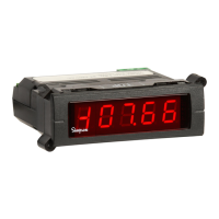
7. Meter: A 0-100μA DC full scale, taut-band movement
with end markings of -10 dB and +10 dB and
1 dB divisions starting from -5 dB. The upper
end of the scale includes a BATT OK section.
8. Calibration Adjustment: This screwdriver adjustment, located under
a metal cap on the side of the Instrument, is
used to calibrate the 886-2. The Simpson
Model 890-2 Sound Level Calibrator, is de-
signed to calibrate the 886-2. The calibration
procedures are contained in the operator’s
manual for the 890-2.
9. Battery Compartment: The battery compartment, which is totally
separated from the electronics, houses the
battery
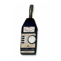
4.3 Sound Level Measurements
To obtain sound level measurements with the 886-2.
a. Turn on the Instrument and select the desired measurement range. To en-
sure accurate results, check the battery every time sound level measure-
ments are made.
b. When the Instrument is hand-held, orientate the microphone approximately
45° to 70° with respect to the horizontal plane and at an angle of 70° with
respect to incoming sound waves.
c. For OSHA compliance measurement set FAST/SLOW switch to SLOW, the
range switch to OSHA, and depress “A” weighting push-button. Read exact
dB(A) on red OSHA arc.
d. For other applications, select the desired range, weighting, and response. If
the meter fluctuations are in excess of 3 dB set the response to SLOW posi-
tion.
NOTE: With the range switch set to any of the other ranges (black numerals), the
black indicator, and the switch position corresponds to zero (0) indication. For
example, if switch is set to 90, and the indication is 5, add 5 to 90 to obtain 95 dB
level.
e. To conduct impact noise checks, set FAST/SLOW switch to FAST, dB range