Do you have a question about the Simrad S5100 and is the answer not in the manual?
Covers product changes, liability disclaimers, governing language, copyright, warranty, and compliance statements.
Details the intended audience and explains important text conventions used in the manual.
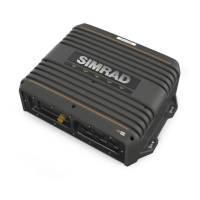
Provides a high-level description of the S5100 as a networked triple CHIRP sonar module.
Lists and illustrates all components supplied with the S5100 sonar module.
Identifies the location and purpose of all connectors and status LEDs on the S5100 unit.
Provides instructions and considerations for selecting an appropriate mounting location for the S5100.
Refers to separate instructions for the physical installation of the sonar transducer.
Offers essential do's and don'ts for routing and connecting cables to prevent damage and ensure functionality.
Explains the procedure for safely grounding the unit for added protection.
Details the power supply requirements and connection methods for the S5100 module.
Illustrates how to connect the S5100 to Multi-Function Displays via Ethernet for data sharing.
Describes how to connect various types of transducers, including 7-pin, 9-pin, and bare wire types.
Specifies the correct connection procedure for transducers featuring two element connectors.
Explains the meaning of different LED states for power, network, and sonar channels for diagnostics.
Outlines minimal preventative maintenance required for the unit, focusing on external checks.
Provides guidance on visually inspecting and securing the unit's connectors.
Details the steps for updating the S5100's software via a connected display unit and memory card.
Lists available spare parts for the S5100 module with their corresponding part numbers.
Directs users to a guide for selecting compatible transducers for the S5100.
| Brand | Simrad |
|---|---|
| Model | S5100 |
| Category | Control Unit |
| Language | English |