GD10P User Manual Page 28 of 44 850-811250-Rev.06b
6.5 Fault finding
The internal microprocessor performs
continuous self-testing of optical and
electronic functions.
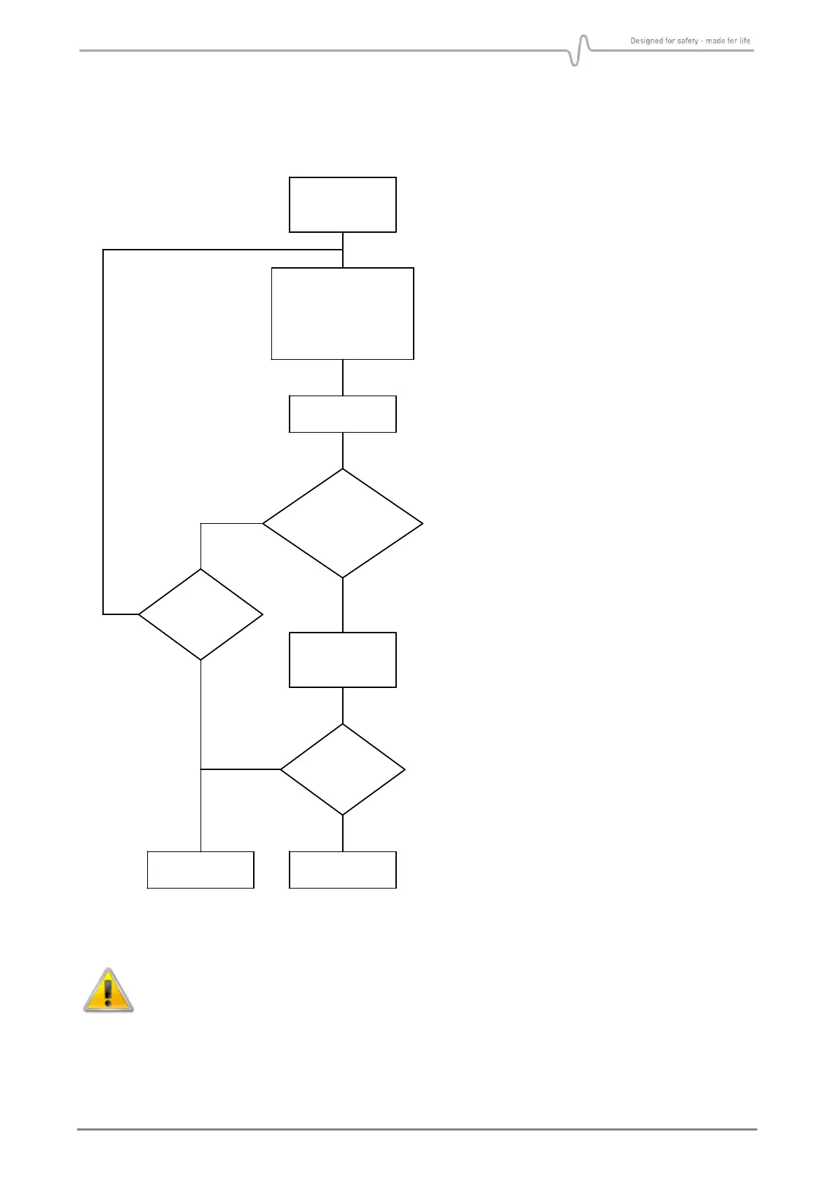
If a fatal error should occur in the
electronics or optics, the processor will
generate a 0mA output signal, indicating
detector failure. The detector should then
be checked according to flow chart on the
left. Do not return the instrument to the
supplier for repair if this test has not been
performed.
If the IR transmission in the optical path
is attenuated to 50-70% of its original
value, the output signal will go down to
Early Dirty Optics (see section 5.1 for
further details).
If the IR transmission is further
attenuated, the output signal will go
down to Dirty Optics (fault). In this
condition the detector will not detect gas
(see section 5.1 for further details).
If the optics are contaminated, wipe them
with a clean cloth and mild detergent
according to instructions in section. 6.1.
The optics must be cleaned even if they
appear not to be contaminated.
A signal output equal to 0 mA can be due to a power supply failure. Check first that
voltage supply at detector terminal is between 18VDC and 32VDC.
Avoid direct light on lens and mirror if testing without the Weather Protection.
Ensure that no gas is present in the measuring chamber when testing.