WIRING
Three-phase SIMUBOX motors have been made to be exclusively wired with 1.5 mm² diameter cables for the power
supply connection and with 0.75 mm² diameter cables for the command connection.
Attach the cables to prevent contact with moving parts.
- The installer must ensure that the installation of the motorization complies with the electrical installation instructions
in force in the country of commissioning.
- Always make a loop on the power cable to prevent water penetration into the actuator.
- Cables passing through a metal wall must be protected and insulated by a sleeve or sheath.
- The motor casing must be connected to a rigid conduit.
- Use the traction stop.
- The connection of the power supply conductors must only be made after installing the motor on its support.
- Cables have to be stripped on 8 mm.
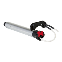
Installation diagram:
EN
4/6
S1
S2
S1
S2
5
1 2
3
4
i
Traction stop has to be used.
Secu Mot inputs have to be wired in
order to operate the motor.
There are 2 auxiliary contacts available
which allow, for example, to know if the door
is in open or closed position.
Outputs are made on a 3 terminal connector
which is xed on the cover plate.
Outputs of auxiliary contacts on 3 terminal
connector :
• 1 terminal Ri S1 for S1
• 1 terminal Si Com pour common
• 1 terminal Ri S2 for S2
Type of output : dry contacts normally open
Capacity : 1A under 24Vdc
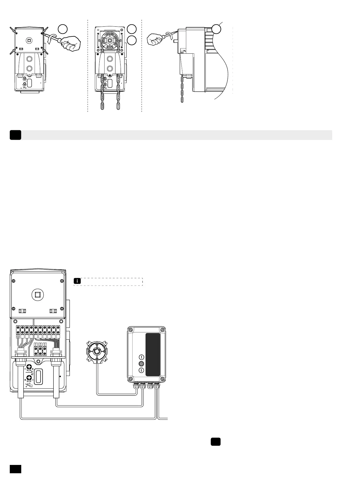
4.2 - Mounting of chain manual override
1. Remove the chain cover by
unscrewing the 4 screws.
2. Install the chain.
3. Pass the chain links in the
chain guide and in the notched
wheel by introducing them in.
4. Replace the cover.
SAFETY BRAKEUVW
Fdc
S1
Fdc
S1
Fdc
S2
Fdc
S2
Secu
Mot
Secu
Mot
SD510
Refer to SD510 control manual