42
Installation and Maintenance
Service Manual
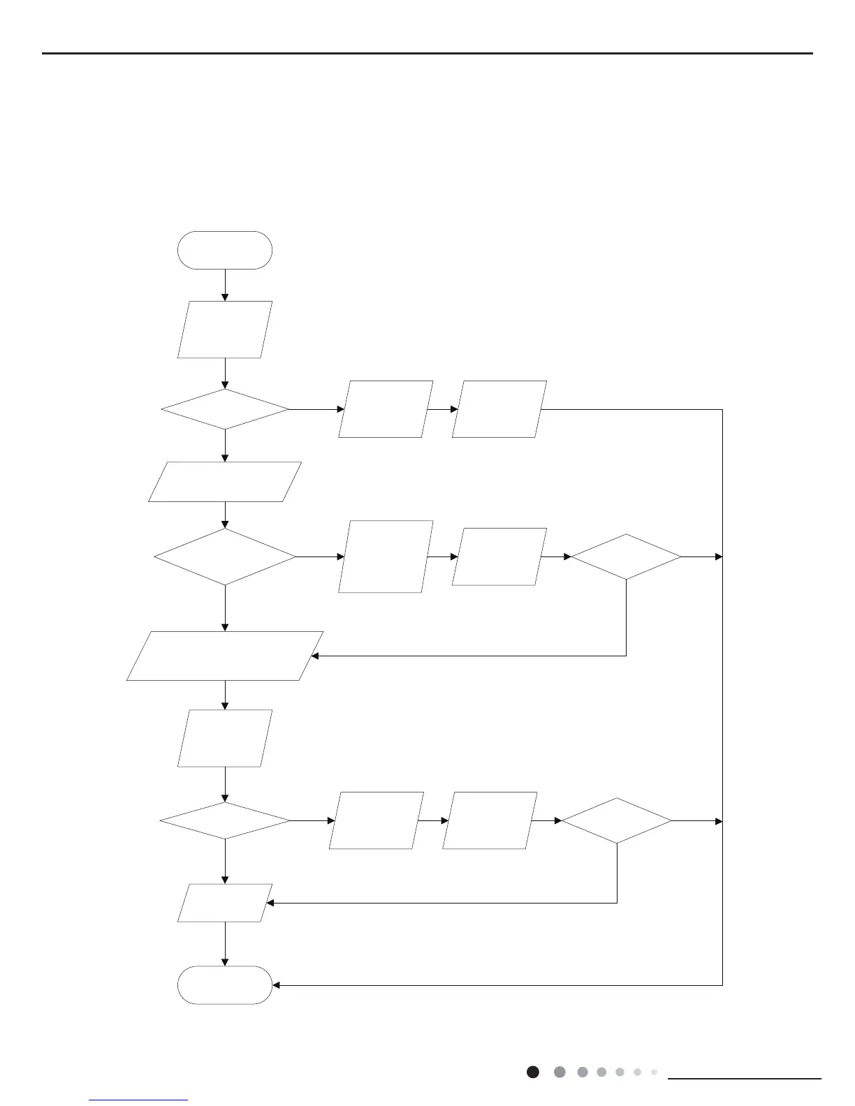
(1) Capacitor charge fault (Fault with outdoor unit) (AP1 below refers to the outdoor control panel)
Main Check Points:
●Use AC voltmeter to check if the voltage between terminal L and N on the wiring board is within 210VAC~240VAC.
●Is the reactor (L) correctly connected? Is the connection loose or fallen? Is the reactor (L) damaged?
Fault diagnosis process:
Outdoot Unit
No
Yes
No
Yes
No
Yes
No
Yes
No
Yes
Turn on the unit
and wait 1 minute
Use DC voltmeter
to measure the
voltage on the two
ends of electrolytic
capacitor
Voltage higher than 200V?
Fault with the voltage
testing circuit on
control panel AP1
Replace the control
panel AP1
Measure the AC voltage between
terminal
L and N on wiring board
XT(power supply)
Voltage within
210VAC~250VAC?
Shut down the power
and repair the power
supply to restore the
range
210VAC~250VAC
power on and
restart the unit
If the fault is
eliminated?
Shut down the power and wait 20 mi
nutes;
or use DC voltmeter to measure the voltage
on the two ends of capacitor , until the
voltage is lower than 20V
Check the
connection of reactor
(L in the Electrical
Wiring Diagram)
If the wiring of
reactor L
is normal?
Connect the reactor
Laccording to Elec-
trical Wiring Diagr-
am correctly
Re-energize and
turn on the unit
If the fault is
eliminated?
End
Replace the control
panel AP1
 Loading...