◆Installation Services—Install Indoor Unit
-18-
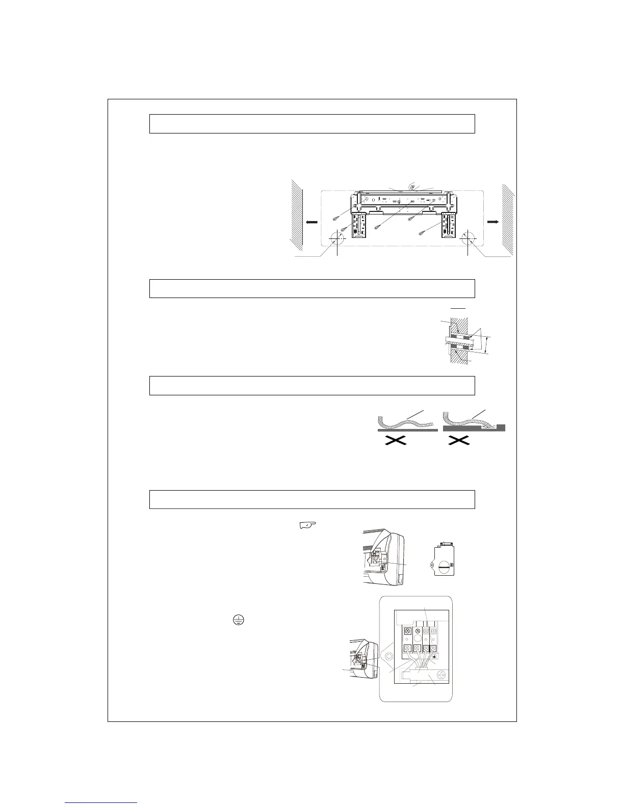
Installing Wall-Mounting Frame
1. Level with plumb line or spirit level. As the drain outlet is on left side, it is better that the left side shall
be lower when adjusting the wall-mounted board.
2. Use screws to secure the
wall-mounting frame on the wall.
3. After installation is completed,
manually pull the wall-mounting frame
to check if it is secured. The mounted
frame shall be able to withstand the
weight of an adult (60 kg) and the
fixing screws shall have relatively
even stress.
Wall Opening and Wall Pipe Installation
1. After deciding the hole position of the fitting pipe according to
Figure 6, drill a declining hole ( 65)
2. To prevent the fitting pipe and the cable passing through the wall
from being harmed and also protect the hollow wall from rats, it is
necessary to install a wall pipe.
Installing Drainage Pipe
1. The flexible drainage pipe must descend
to allow smooth
running of water.
2. Pay attention not to allow twists, ridges and distortion of the
drainage pipe in the layout and not to immerse the outlet in
water.
3. Extended part of flexible drainage pipe passing through the
indoor unit must be wrapped by thermal insulation material.
Connection of Indoor and Outdoor Cables
1. Pull open the front panel from the above. ( page
10 Fig5 (a))
2. Unscrew the screw fixing the covering plate of
terminal board.(Fig 7)
3. Pass the power cable through a separate cable duct
on the back of indoor unit and pull it out from the front.
5. Place the section of power cable with protective pipe
into pressing groove and close the cover plate.
Tighten the fixing screws to clamp the connecting
cable.
6. Install the front panel back into position
Do not immerse
into water.
Twist
Ridge
Ø
65
Indoor
Outdoor
Wall
pipe
Seal pad
Proection
sleeve pipe
Wrenched
Covering plate
Power
Connection
Cable
Fig 7
Terminal Board
Brown
Blue
Yellow-green
Power
Connection
Cable
Cable
Groove
Fig 8
4. Connect the blue wire of the power connection cables
to the “N(1)”terminal of the terminal board, connect
the black wire to the “2”terminal, and connect the
brown wire to the“3”terminal and connect the
yellow-green wire to the“ ”terminal (See Fig. 8).
N(1) 2 3
Black
Ø
Indicated at the
middle position
Level Meter
More
Than
150mm
from
e Wath ll
Left Side
φ65mm
(Wall Hole for
Rear Exit-Tube)
Right Side
φ65mm
(Wall Hole for
Rear Exit-Tube)
Wall
More
Than
150mm
from
the Wall
Wall
Fig 3