Service Manual
5. Electrical Part
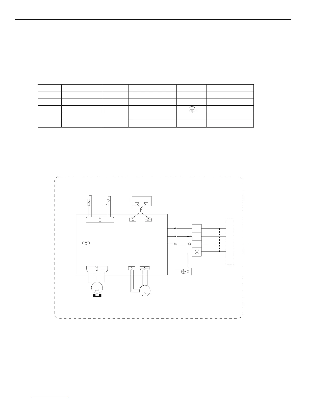
5.1 Wiring Diagram
● Indoor Unit
●Instruction
Symbol Symbol Color Symbol Symbol Color Symbol Name
WH White GN Green CAP Jumper cap
YE Yellow BN Brown COMP Compressor
RD Red BU Blue Grounding wire
YEGN Yellow/Green BK Black / /
VT Violet OG Orange / /
Note: Jumper cap is used to determine fan speed and the swing angle of horizontal lover for this model.
SWING-UD
M2
AC-L
BN
BK
BU
EVAPORATOR
CAP
PE
YEGN
JUMP
DISP2
SWING
N
COM-OUT
BK
BN
3
XT
2
N(1)
BU
YEGN
DISP1
DISPLAY BOARD
TERMINAL
RECEIVER AND
MOTOR
BLOCK
M1
PGPGF
FAN
MOTOR
OUTDOOR UNIT
θ
RT1
RT2
TUBE TEMP.
SENSOR
T-SENSOR
θ
SENSOR
ROOM TEMP.
AP2
PRINTED CIRCUIT BOARD
AP1
CONNECTING
CABLE
 Loading...