22
①
the air conditioning unit due to electromagnetic interference.
Smart zone
controller
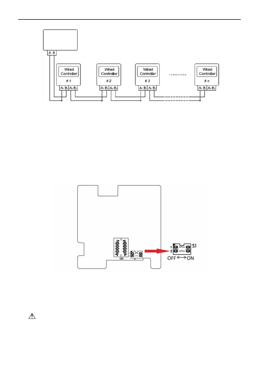
Fig. 27
Fig. 27
shows schematic diagram of DIP switch. There is a 2-bit DIP switch on the main board of wired
controller SWC-04. As for the last #n wired controller in the control system, the 1-bit and the 2-bit of the DIP
switch should be manually pulled to position “on” and position “off” respectively. The DIP switches of other
wired controllers should be kept at the initial ex-factory status (1-bit and 2-bit are set at position “off”).
Wired Controller SWC-04
CAUTION!
Please pay special attention to the followings during the connection to avoid the malfunction of
.
Separate the signal and communication lines of the wired controller from the power
Fig. 26
Fig. 26
shows the schematic diagram of control system connection. SWC-04 can connect the smart zone
controller (integrated control system). “n” indicates the number of communication node address
(
programmable wired controller SWC-04). The complete system is composed of the smart zone
controller, wired controller SWC-04 and communication cable. The wired controller SWC-04 can support
16 communication node addresses at the most (n≤16).
Terminal A and terminal B of the smart zone controller are respectively connected to the corresponding
communication needle stand terminal of the #1wired controller by the communication cable; the other
needle stand of #1 wired controller is connected to the #2 wired controller through the telecommunication
cable and so forth until connect to the #n wired controller. Except the last wired controller in the control
system (only use CN2 or CN3, and the other one will not be connected), there’s no the sequence and the
importance for the wired controller. The series number in the figure is only for the sake of clarity.