User Manual of A90 Series Inverter
40
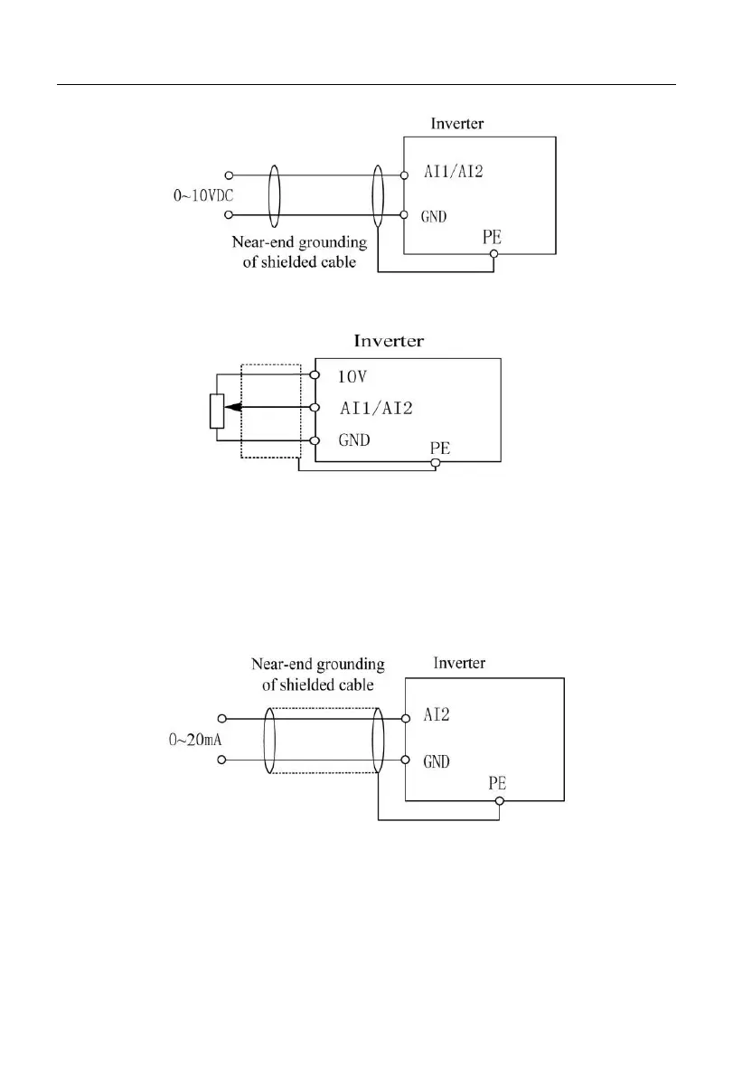
(a)
(b)
Fig. 3-12 AI1/AI2 Terminal Wiring Diagram
3.3.3.2
Wiring of the input analog current signal of AI2 terminal:
When the AI2 terminal is in the mode of analog current signal input, the switch S2 on the terminal block
is set to the current mode.
Fig. 3-13 Wiring Diagram of External Current Source and AI2 Terminal
3.3.4
Wiring of multi-function input terminal
Among the multi-function input terminals of the A90 series inverter, the common terminal is COM (the
terminals COM and GND are connected internally for the A90-4T017B model and below). The digital input
terminal and COM are valid when short-circuited and invalid when disconnected (NPN mode).
 Loading...
