User Manual of A90 Series Inverter
41
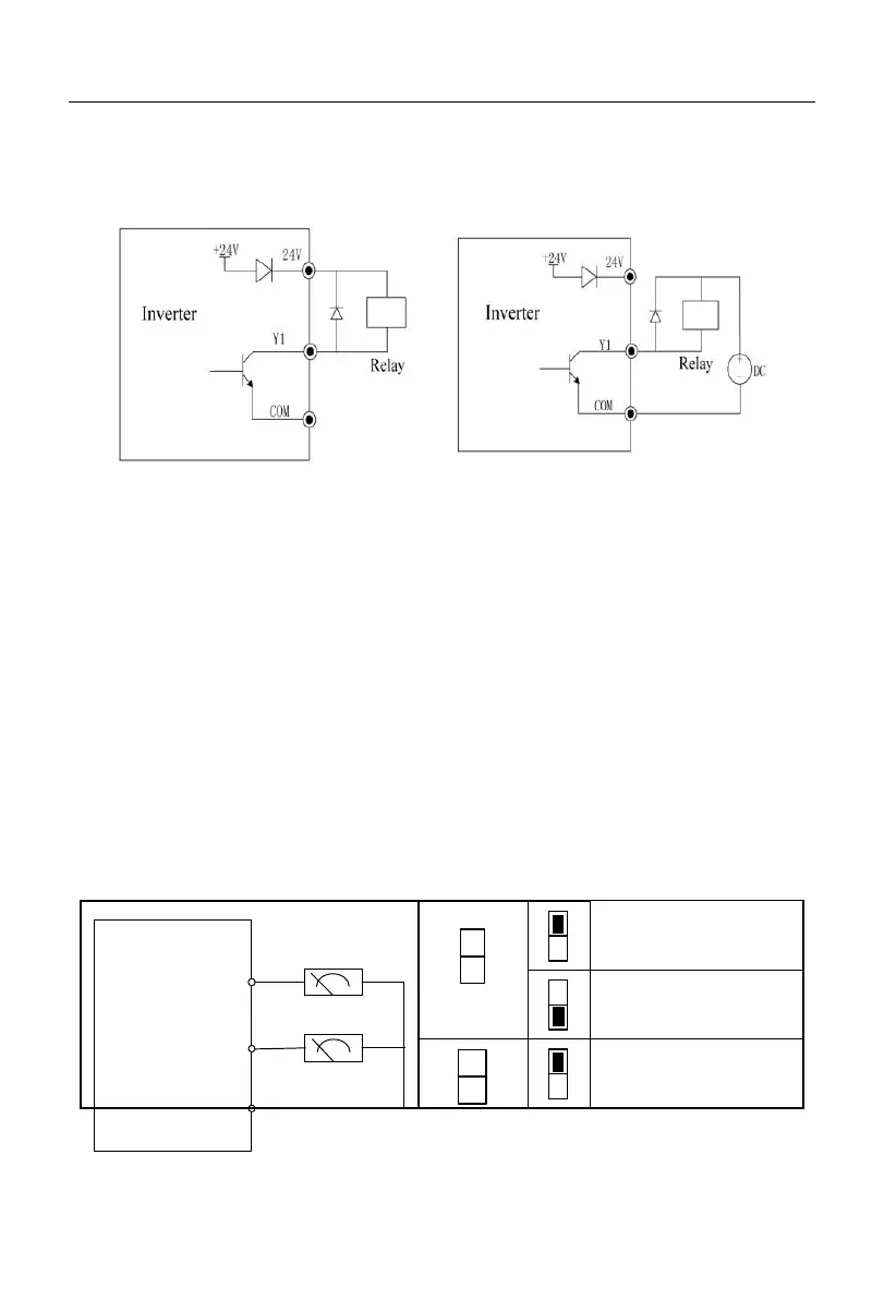
3.3.5
Wiring of multi-function output terminals
The multi-function output terminal Y1 is powered on by the internal 24V power supply of the inverter or
an external power supply, as shown in Fig. 3-14:
a: Use of internal power supply b: Use of external power supply
Fig. 3-14 Wiring of Multi-function Output Terminals
Note:
(1) An anti-parallel diode must be included in the relay wire package. The absorption circuit components
should be installed at both ends of the coil of the relay or contactor.
(2) For the A90-4T017B model and below, the terminals COM and GND should be connected internally.
3.3.6
Wiring of analog output terminals
The analog output terminals (M1 and M2) are connected with external analog meters
to represent physical quantities. The dial switch is set to the output current mode (0-20mA)
or (0-10V). M1 corresponds to S3, and M2 corresponds to S4 (for the inverter of 90KW
and power, M1 corresponds to S2, and M2 corresponds to S3). M1 only outputs the voltage
(0-10V). Wiring of the dial switch and terminals is as follows:
M2 is for analog
voltage output
M2 is for analog
current output
M2 is for analog
voltage output
 Loading...
