User Manual of A90 Series Inverter
169
F05.00=0: linear V/F
It is suitable for ordinary constant-torque loads.
F05.00=1: multi-point V/F
It is suitable for special loads such as dehydrators, centrifuges and cranes. Any V/F
relationship curve can be obtained by setting the parameters F05.01 to F05.06.
F05.00=2/3: 1.3
th
power/1.7
th
power of V/F
It is a VF curve between the linear VF and square VF.
F05.00=4: square V/F
It is suitable for centrifugal loads such as fans and pumps.
F05.00=5:
VF complete separation mode
In this case, the output frequency and output voltage of the inverter are independent of
each other. The output frequency depends on the frequency source, and the output voltage
is determined by F05.07 (VF separation voltage source).
The VF complete separation mode is usually applied in induction heating, inverter
power supply, torque motor control, etc.
F05.00=6:
VF semi-separation mode
In this case, V and F are proportional, but their proportional relationship can be set by
the voltage source F05.07. In addition, the relationship between V and F is also related to
the rated voltage and rated frequency of the motor in the F1 group.
Assuming that the voltage source input is X (X is 0 to 100%), the relationship between
the output voltage V and frequency F of the inverter is:
V/F=2*X* (rated voltage of the motor)/(rated frequency of the motor)
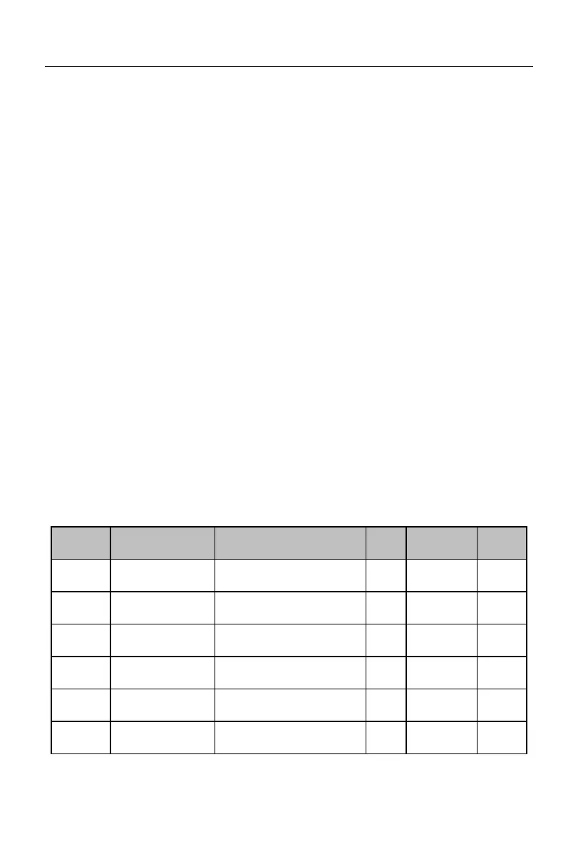
Frequency point F1
of multi-point VF
Voltage point V1 of
multi-point VF
0.0~100.0 (100.0 = Rated
voltage)
Frequency point F2
of multi-point VF
Voltage point V2 of
multi-point VF
Frequency point F3
of multi-point VF
F05.03 to rated frequency of
motor (reference frequency)
Voltage point V3 of
multi-point VF
 Loading...