User Manual of A90 Series Inverter
170
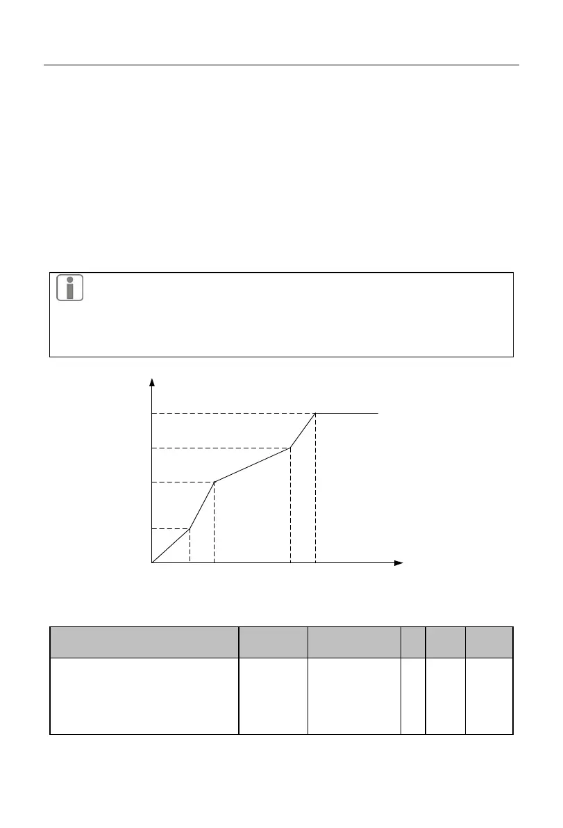
The code parameters F05.01 to F05.06 are valid when the multi-point polyline VF is
selected (F05.00=1).
All V/F curves are dependent on the curve set by the percentage of input frequency
and the percentage of output voltage, linearized in sections within different input ranges.
The rated frequency of the motor is the final frequency of the V/F curve, and also the
frequency corresponding to the highest output voltage. Percentage of the input frequency:
rated frequency of the motor = 100.0%; percentage of the output voltage: rated voltage U
e
of the motor = 100.0%.
The relationships of the three voltage points and frequency points must meet the
following requirements: V1
<
V2
<
V3, F1
<
F2
<
F3;
If the slope of the V/F curve is too large, an “overcurrent” fault may occur. Particularly, if
the low-frequency voltage is too high, the motor may be overheated and even burnt, and
the inverter may be subject to overcurrent stall or overcurrent protection.
Output voltage (%)
Rated voltage of
motor
V3
V2
V1
F1 F2 F3 Rated frequency of motor
Output frequency
(%)
Fig. 7-19 Schematic Diagram of Multi-point Polyline V/F Curve
Voltage
source of VF
separation
mode
0: digital setting
of VF separation
voltage
1: AI1
2: AI2
3-4: retention
 Loading...