User Manual of A90 Series Inverter
192
the PLC process will be performed every time the inverter is started.
The PLC power-down memory is to record the current simple PLC running times
(F18.10), running stage (F18.11), and running time at the current stage (F18.12) before the
memory is powered off. The inverter will continue to run from the memory stage when the
inverter is powered on again. If you choose no memory, the PLC process will be performed
every time the inverter is powered on.
0: s (second)
1: min (minute)
In order to meet different working conditions, the running time involved in the PLC
function is set to a numerical value. Its specific meaning needs to be set in conjunction with
the simple PLC time unit (F08.18). At present, there are two types of unit: second and
minute.
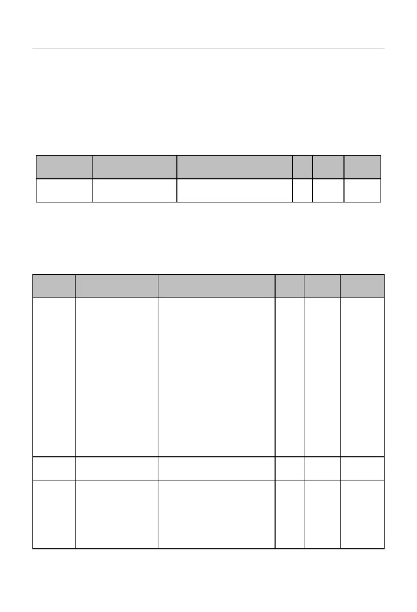
Setting of the first
segment
Ones place:
Running
direction options
0: forward
1: reverse
Tens place:
Acceleration and
deceleration time options
0: acceleration and
deceleration time 1
1: acceleration and
deceleration time 2
2: acceleration and
deceleration time 3
3: acceleration and
deceleration time 4
Running time of the
first segment
Setting of the second
segment
Ones place:
Running
direction options
0: forward
1: reverse
Tens place:
Acceleration and
deceleration time options
 Loading...