User Manual of A90 Series Inverter
191
★
The last segment refers to the segment that is not set to 0, judged from the running
time (F08.48) of the 15
th
segment toward the 1
st
segment.
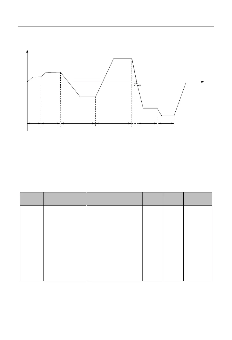
T1 T2 T4 T5 T12 T13
1
2
4
5
12
13
Time (s)
Output
frequency (Hz)
Fig. 7-25 Schematic Diagram of Simple PLC Operation
Fig. 7-25 shows the operation diagram in the running mode “0: stop after a single run”.
Since the running time of the 3
rd
segment is set to 0 (F08.24=0.0), the 3
rd
segment will not
be put into actual operation. The running time of the 14
th
and 15
th
segments is set to 0
(F08.46=0.0, F08.48=0.0), so the last segment is the 13
th
segment, and the inverter will be
stopped after running in the 13
th
segment.
Simple PLC
memory options
Ones place:
Stop
memory options
0: no memory (from the
first segment)
1: memory (from the
moment of stop)
Tens place:
Power-down
memory options
0: no memory (from the
first segment)
1: Memory (from the
power-down moment)
The PLC stop memory is to record the current simple PLC running times (F18.10),
running stage (F18.11), and running time at the current stage (F18.12). The inverter will
continue to run from the memory stage during next operation. If you choose no memory,
 Loading...