User Manual of A90 Series Inverter
204
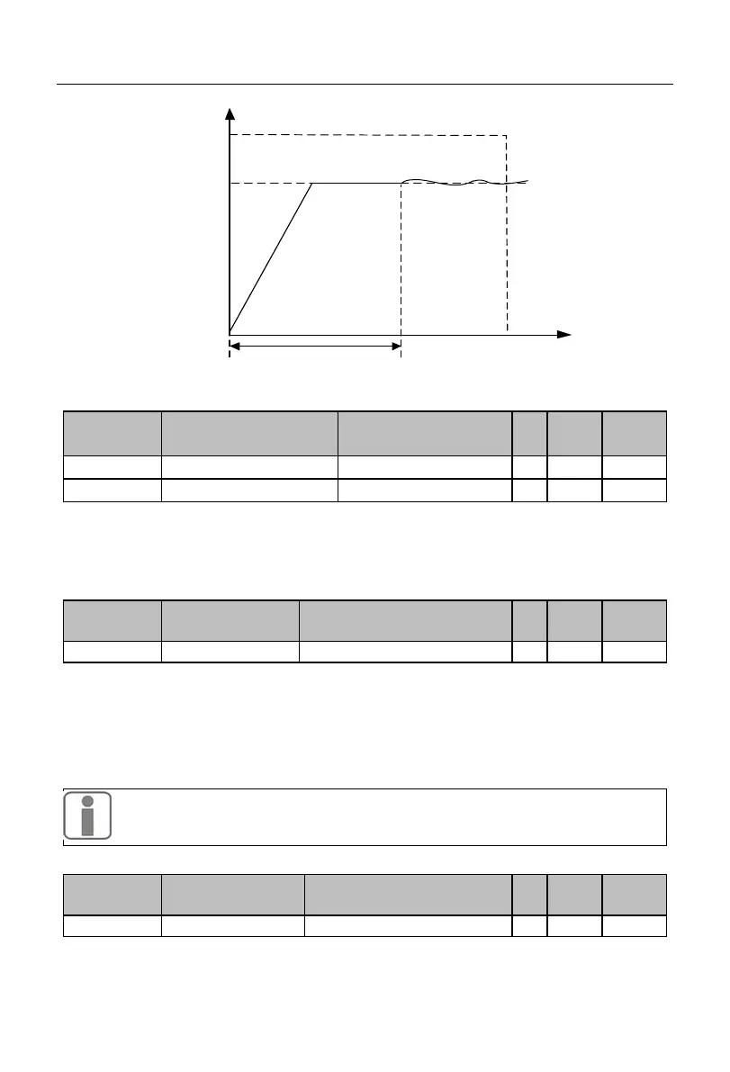
Time
Output
frequency
0
Initial PID
value
F09.14
Holding time of initial
PID value (F09.15)
Fig. 7-28 Schematic Diagram of Initial PID Output
Upper limit of PID output
Lower limit of PID output
The PID output is limited. The output range of the PID module in the whole process is
(F09.17, F09.16). That is, if the actual adjustment result is beyond this range, the output
will be based on the boundaries.
0.00-100.00 (0.00: invalid)
When the deviation between the PID setting and feedback is less than or equal to the
deviation limit (F09.18), the PID will stop the adjustment. When the deviation between the
setting and feedback is smaller, the output frequency will remain stable. This is valid for
some closed-loop control applications.
If the input terminal function “41: process PID pause” is valid, the PID will also
stop the adjustment. Users need to use these two modes together.
The differential (D) component of the PID regulator must not be greater than the PID
 Loading...