User Manual of A90 Series Inverter
203
prevail; when the function code is set to 1, the PID parameters will be selected according to
the status of the input function “43: PID parameter switching”; when the function code 2 is
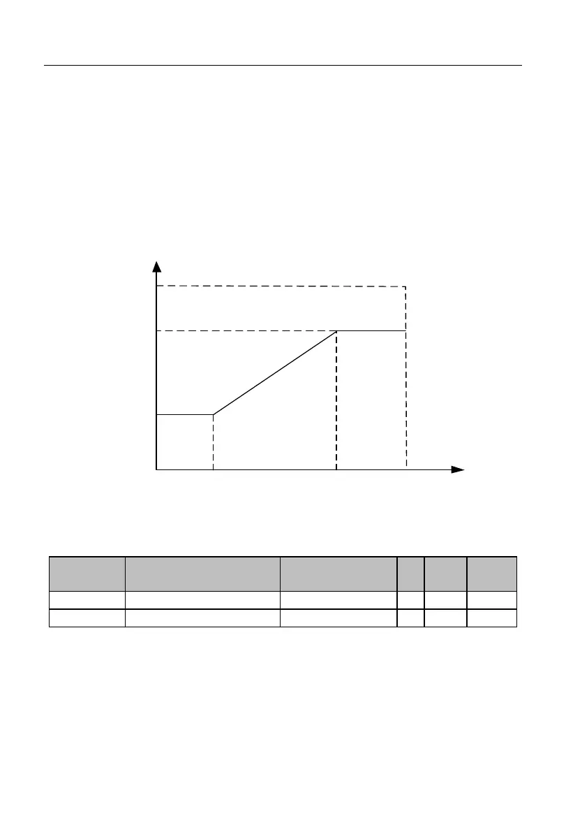
used, the PID parameters will be selected according to the absolute value |e(k)|
(=|setting-feedback|) of the current deviation and the relationship between the function
codes F09.12 and F09. Or, the linear difference may be used.
In the case of “F09.12≤|e(k)|≤F09.13”, the current PID parameters are obtained
through linear interpolation of the first and second groups of parameters. The specific
principle is shown by the intermediate segment in Fig. 7-27.
|Deviation|
PID
parameters
Parameter
1
100.00%
0
Parameter
2
Switching
deviation 1
Switching
deviation 2
Fig. 7-27 Schematic Diagram of Automatic Switching of PID Parameters based on
Deviation (F19.11=2)
PID initial value holding time
The inverter starts running, and the process PID module constantly outputs the initial
PID value (F09.14) for the initial PID holding time (F09.15). Then the output is adjusted by
the PID based on the deviation. Specific effects are shown in Fig. 7-28.
When the initial PID holding time is set to 0.00s, i.e. F09.15=0.00, the initial PID
output function will be invalid.
 Loading...