User Manual of A90 Series Inverter
233
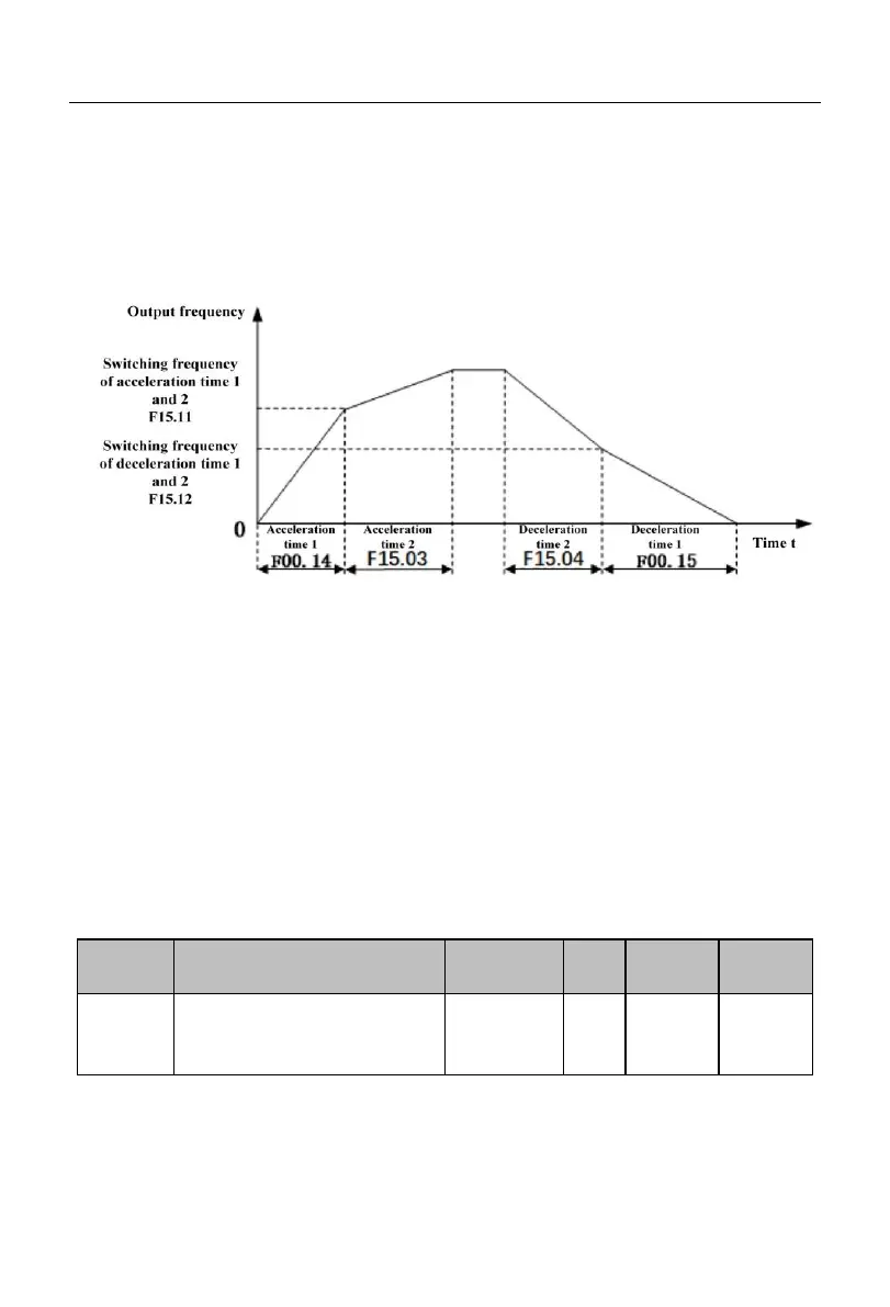
If the motor 1 is running at the normal (e.g. non-PLC/PID) speed (e.g. non-torque) and
the acceleration/deceleration time terminals (19: acceleration and deceleration time terminal
1; 20: acceleration and deceleration time terminal 2) are invalid, the
acceleration/deceleration time 1 and acceleration/deceleration time 2 can be switched by
setting F15.10 to 1, as detailed in Fig. 7-33.
Fig. 7-33 Schematic Diagram of Automatic Switching of Acceleration and Deceleration
Time
During acceleration, if the output frequency is less than the switching frequency of the
acceleration time 1 and 2 (F15.11), the acceleration time 1 will be the current valid
acceleration time; otherwise, the acceleration time 2 will be the current valid acceleration
time.
During deceleration, if the output frequency is less than the switching frequency of the
deceleration time 1 and 2 (F15.12), the deceleration time 1 will be the current valid
deceleration time; otherwise, the deceleration time 2 will be the current valid deceleration
time.
Under different working conditions, the acceleration and deceleration time
requirements may vary greatly. The system provides three acceleration and deceleration
time units, depending on the function code F15.13. F15.13=1 means that the
Acceleration and deceleration
time unit
 Loading...