User Manual of A90 Series Inverter
236
Output frequency
detection FDT1
0.00 to maximum frequency
F00.16
Output frequency
detection FDT2
0.00 to maximum frequency
F00.16
Output
frequency (Hz)
Output
frequency
detection 1
Output
terminal 1
0
Invalid
Hysteresis 1
Valid
Output
frequency
detection 2
Hysteresis 2
(negative)
Output
terminal 2
Invalid
Valid
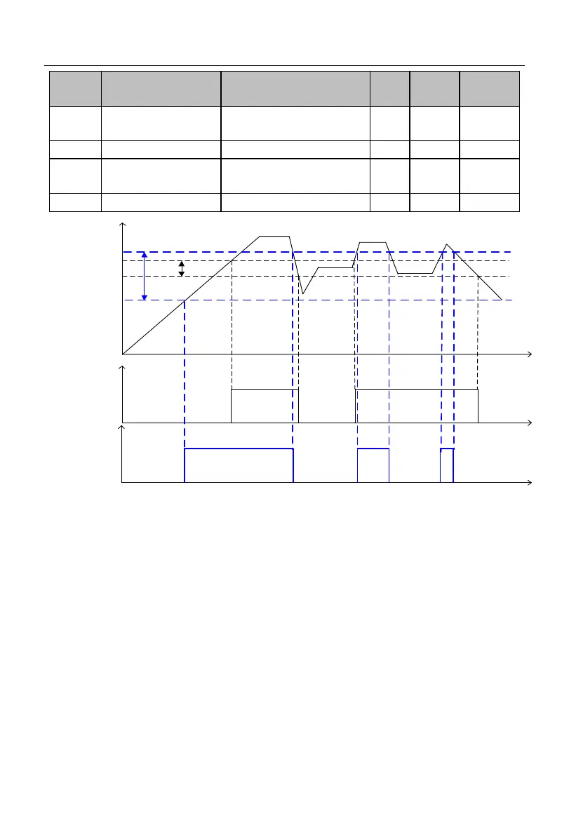
Fig. 7-36 Schematic Diagram of FDT Detection
As shown in Fig. 7-36, when the multi-function output terminal or relay output is set
to “3: output frequency detection FDT1” or “4: output frequency detection FDT2” and the
inverter is running:
1. If the hysteresis is positive and the |output frequency| is greater than the result of “output
frequency detection FDT1/2” (F15.21/F15.23), the corresponding function terminal will
output the active level; if the |output frequency| drops to less than the result of “output
frequency detection FDT1/2 (F15.21/F15.23) - FDT1/2 hysteresis (F15.22/F15.24)”, the
corresponding function terminal will output the inactive level; and if the |output frequency|
is within the range of (output frequency detection - hysteresis, output frequency detection),
the output level of the corresponding function terminal will remain unchanged.
 Loading...