User Manual of A90 Series Inverter
34
MCCB
Inverter
Noise
filter
Control
device
Radio
device
Signal lines
Transmission
interference
IM
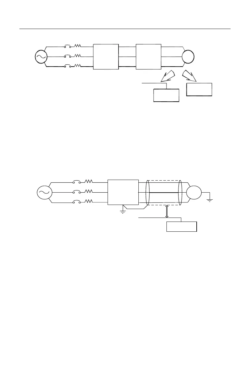
Fig. 3-7 Noise Filter Installation on Output Side
3.2.5.7
Solution to inductive interference
To suppress the inductive interference on the output side, all output cables can be laid
in the grounded metal tubes, in addition to the aforesaid installation of the noise filter.
When the distance between the output cable and signal line is greater than 30 cm, the
impact of inductive interference will decrease significantly, as shown in Fig. 3-8.
MCCB
Signal lines
> 30cm
Metal tube
Control
device
Inverter
IM
Fig. 3-8 Solution to Inductive Interference
3.2.5.8
Solution to RF interference
The input cable, output cable and inverter itself generates RF interference, which can
be reduced by installing noise filters on the input and output sides and shielding the inverter
body with an iron box, as shown in Fig. 3-9.
 Loading...