User Manual of A90 Series Inverter
43
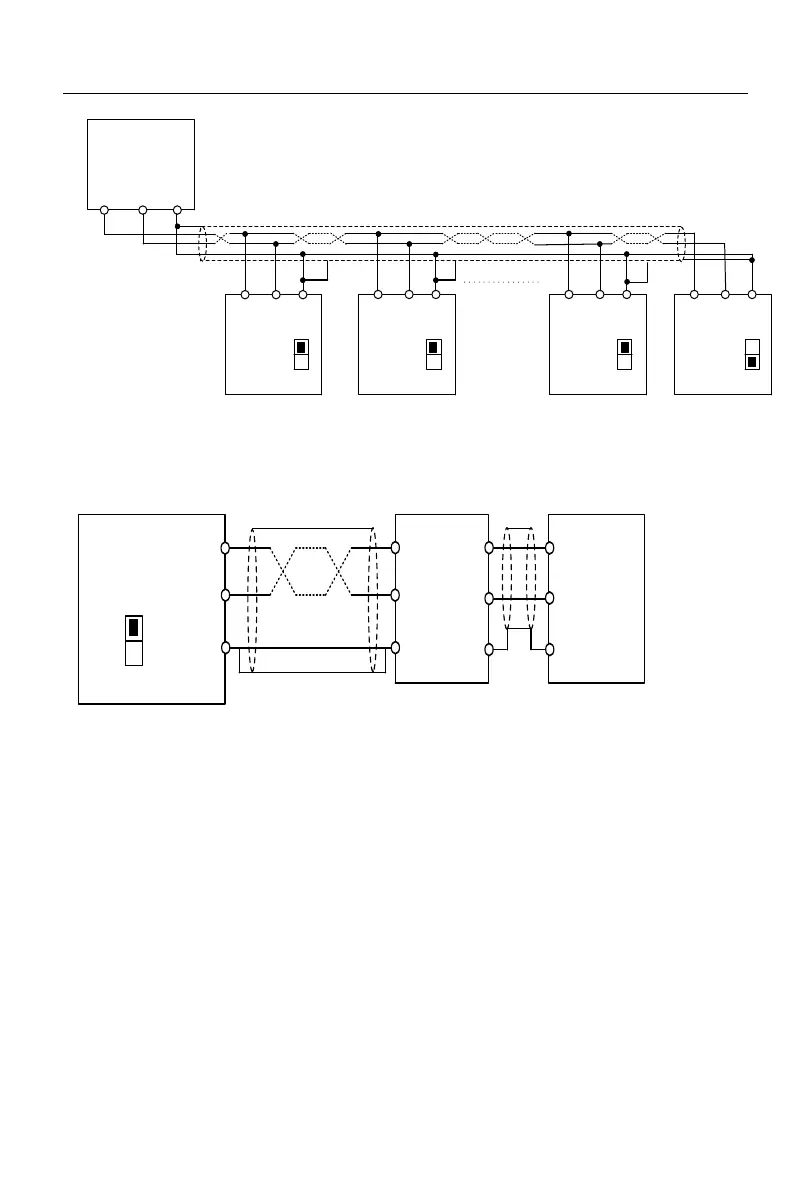
A-
Inverter
A+ GND
RS485
communication
interface of host
+
terminal
-
terminal
A-
Inverter
A+ GND A-
Inverter
A+ GND A-
Inverter
A+ GND
S5/S1
OFF
S5/S1
OFF
S5/S1
OFF
S5/S1
ON
GND
Fig. 3-16 Wiring of Communication Terminals of Multiple Inverters
Connection to the host via RS485/RS232 adapter for communication:
A-
Inverter
A+
GND
RS485/RS232
adapter
RS232
communication
interface of
host
S5/S1
OFF
Fig. 3-17 Communication Terminal Wiring
3.3.8
Wire and screw dimensions of control circuit
In order to reduce the interference and attenuation of the control signal, the
control signal connection cable should be less than 50 m long, and the distance
between the control signal connection cable and power line should be greater
than 30 cm. Use the twisted-pair shielded cable when analog signals are
externally inputted.
It is recommended to use the wire with a diameter of 0.5-1 mm
2
in the control
circuit.
The terminal block of the A90 series inverter is composed of through-type
control circuit terminals. Install it with the PH0 Phillips screwdriver. The
 Loading...