User Manual of A90 Series Inverter
42
M2 is for analog
current output
Note: 1: For the inverter of 90KW and above, the switch S2 is unavailable and M1
is for analog voltage output.
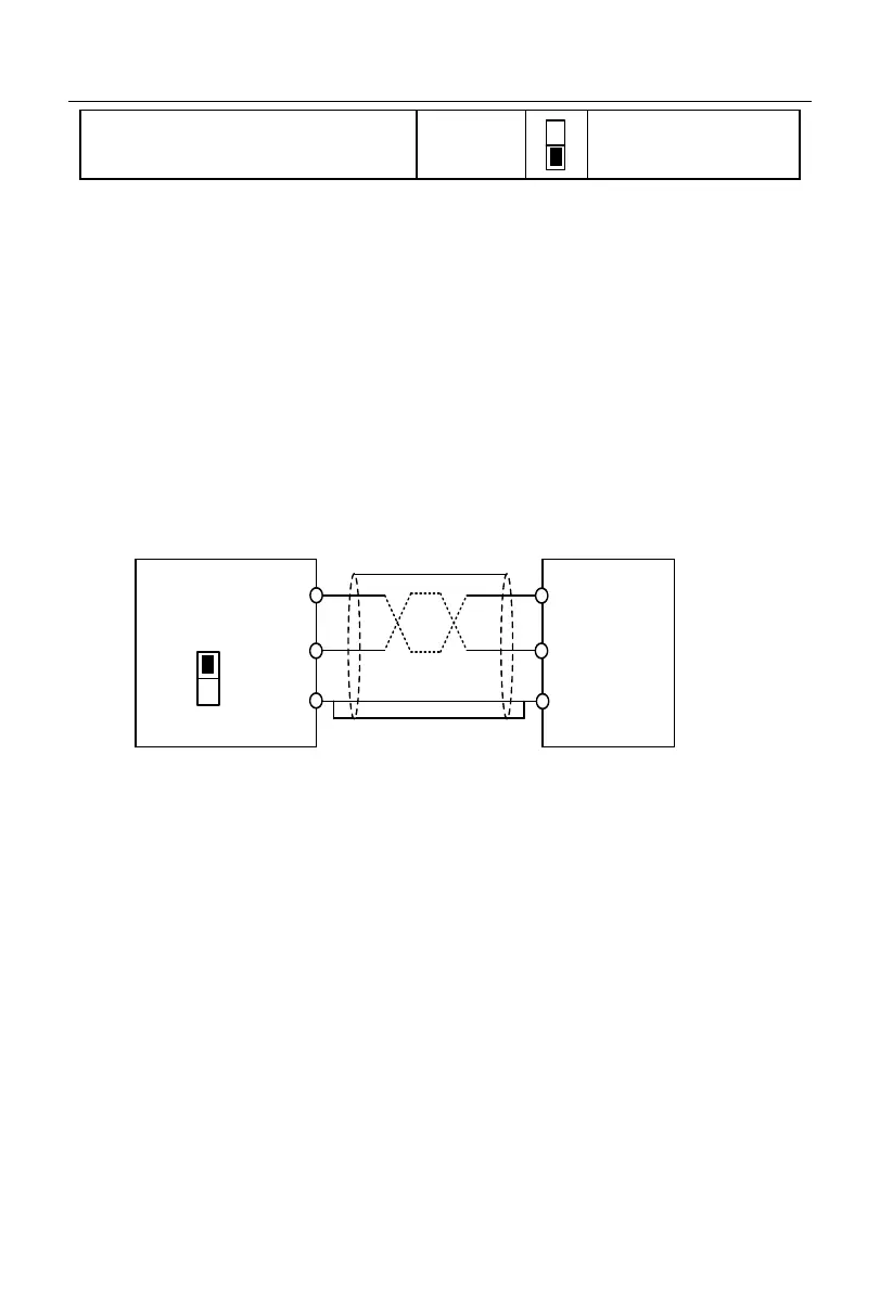
3.3.7
Wiring of 485 communication terminals
The communication terminals A+ and A- are the RS485 communication interfaces of
the inverter. The online control of the host (PC or PLC controller) and inverter is performed
through the connection and communication with the host. The connection of the RS485 and
RS485/RS232 adapters to A90 series inverter is shown in Fig. 3-15, Fig. 3-16 and Fig.
3-17.
Direct connection of the RS485 terminal of a single inverter to the host for
communication:
A-
Inverter
A+
GND
RS485
communication
interface of host
+
terminal
-
terminal
GND
S5/S1
OFF
Fig. 3-15 Communication Terminal Wiring of Single Inverter
Note: 1: The resistor switch S5 is used for the 458 communication terminal of the
inverter of 75KW and below, and S1 for the inverter of 90KW and above.
Connection of the RS485 terminals of multiple inverters to host for
communication:
 Loading...