11
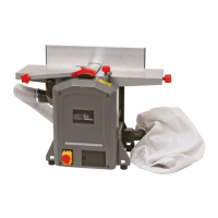
-The dust collector is so positioned that both keys E are in line with the longitude holes D. Then push both
keys E into the longitude holes D. Referring to Fig. 13
Figure 13
SETTING OF GUARD
Height adjustment is made with the lever mounted on the left side of the machine. After lifting the lock
lever the blade cover can be slide ways to set the required stock width for jointing. Push lock lever down to
lock guard extrusion in position. Refer to Figure 14.
5
L
Figure 14
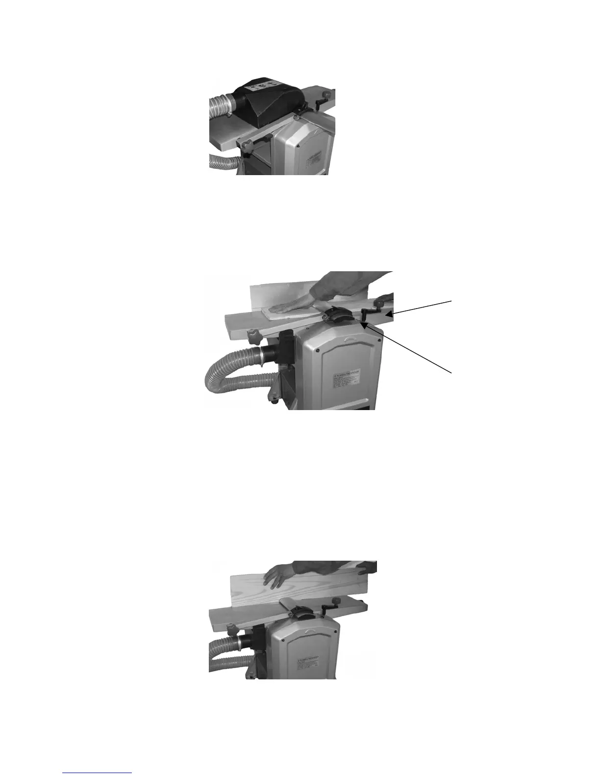
PLANING
The cutting depth is set by handle at the front table plate 5 by means of the scale for cutting depth L.
Cutting depth between 0.5 and 1.5 mm (1/64~1/16 in.) will produce the best surface.
WARNING: The part of the cutter head not used has to be covered by the knife guard.
Take up a working position so that you are always on one side of the machine away from the area directly
in front of or behind the cutter head. Place both hands on the work-piece with the fingers. Do not hold on
to the work-piece edges.
Only work pieces should be planed which rest firmly on the machine and can be safety guided.
Refer to figure 15
Figure 15