16
GETTING TO KNOW YOUR WELDER….cont
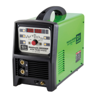
CONTROL PANEL
A. Welding Mode Selector:
HF Tig.
Lift Arc Tig.
MMA (Arc).
B. Pulse Weld Selector.
C. AC / DC mode Selector.
D. Amp Display.
E. Voltage / Second / Percentage / Frequency Display.
F. Voltage / Second / Percentage / Frequency Indicator.
G. Status Indicator:
Power Indicator.
Over Temperature Indicator.
High / Low voltage Indicator.
H. Parameter Display (see page 17 & 18).
I. 2T / 4T Selector.
J. Gas Purge.
K. Parameter Select / Adjust Control.
B
C
A
D
E F
G
H
I
J
K
17
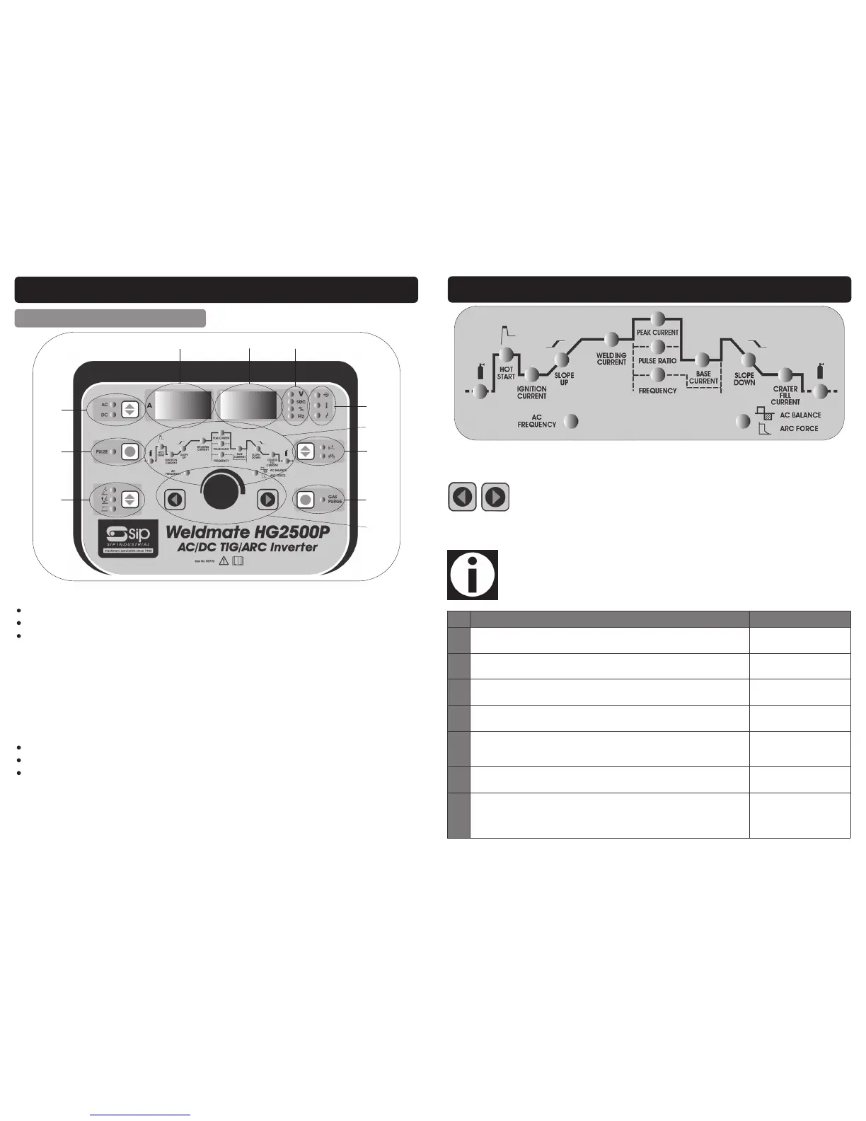
GETTING TO KNOW YOUR WELDER….cont
A
B
C
D
E
F
G
H
I
J
K
L
M
N
Ref. Description Available In Mode
A. Pre Flow Gas Timer: The length of time the welding gas flows before the
arc is initiated.
TIG All Modes
B. Hot Start: Momentarily gives a higher starting current at the beginning of
the weld to assist initiation of the arc.
MMA (ARC)
C. Ignition Current: Ignition/start current, used in conjunction with mode D, is
the welding amps set prior to the slope up timer.
DC Standard TIG
D. Slope Up Time: Is the time it takes for the welder to increase from the igni-
tion (start) current up to the set welding current.
DC Standard TIG
E. AC Frequency: Adjust the output frequency from 0.5 to 200 Hz. (Visibly
alters the width and heat spread of weld pool; improves arc stability and
penetration. Used in conjunction with the AC balance.)
AC & AC Pulse
F. Welding Current: This is the welding current output that is set on the dis-
play. Also known as the output current.
AC & DC Standard TIG
G. Peak Current: Used in conjunction with the base (background) current and
pulse ratio. Peak current replaces the welding current as the primary weld-
ing currently alternating with the base currently. The length of time the
peak and base currents are on is dependent upon the pulse ratio.
AC & DC Pulse
The welding parameters for each mode (where available) are selected by pressing
the Parameter Select buttons:
They are adjusted by turning the Parameter Adjust Control knob. The selected param-
eter will be displayed when the relevant light is illuminated.
Note: The parameter adjust control knob is an infinitely variable type poten-
tiometer and will continue to turn even when the minimum or maximum
limit is reached for each parameter.
 Loading...