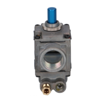
VALVE DESCRIPTION
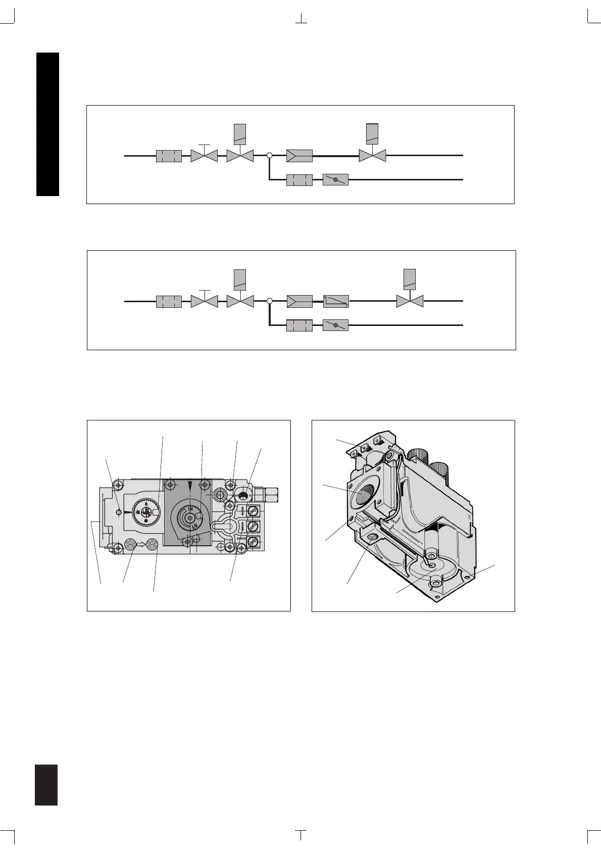
WORKING DIAGRAM
Versions with On/Off adjustment
9
10
11
13
14
12
1. ON/PILOT/OFF Knob 9. Pilot outlet
2. Manual HI-LO adjustment or pressure regulator 10. Main gas outlet
adjustment 11. Flange mounting screw holes
3. Pilot adjustment 12. Additional valve mounting holes
4. Thermocouple connection 13. Alternative TC connection point
5. Mounting for piezo & bracket 14. Thermoelectric unit
6. Inlet pressure test point 15. Inlet
7. Outlet pressure test point
8. Main operator