7
Fig. A
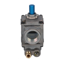
INSTALLING THE VALVE
1. Mount the valve in the desired position.
2. Mount the valve so the flow of gas is consistent with the
gas flow arrows on the valve.
3. Apply a moderate amount of quality pipe compound
(DO NOT USE TEFLON TAPE) to the pipe only, leaving
two end threads bare. On LP installations, use
compound that resists exposure to LP gas.
4. Remove seals over inlet and outlet if necessary
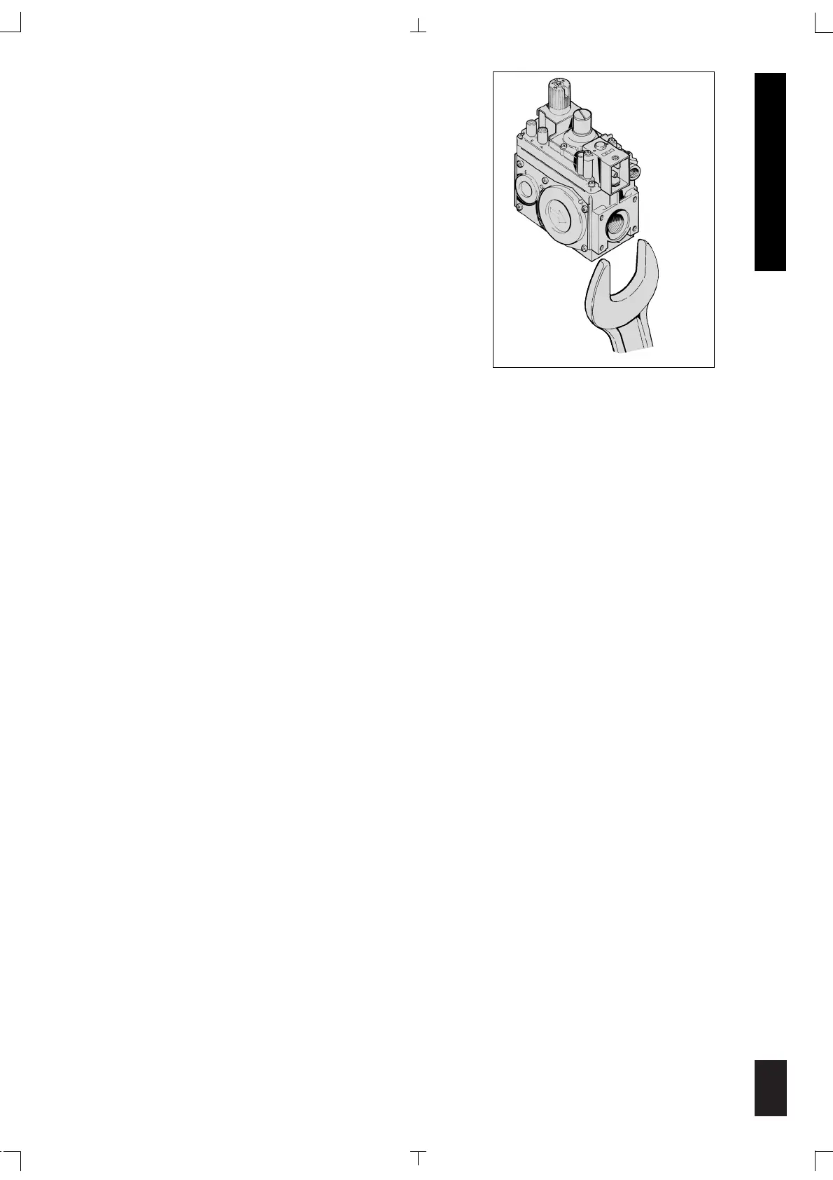
5. Connect pipe to valve inlet and outlet. Place wrench on
valve as shown in (fig A).
6. Thread pipe into the valve until a gas tight seal is
achieved. Typically, for NPT thread, penetration is usually no more than the diameter of the
pipe or 2 and 1/4 turns of thread. Valve distortion or mechanical failure can result if the pipe is
inserted too deeply.
7. Connect pilot tubing to valve with appropriately sized fittings.
8. Confirm gas tight seals with gas leak test.
WIRING
Follow the wiring instructions furnished by the appliance manufacturer, if available, or use the
following general instructions. Appliance manufacturers instructions always supercede these
instructions.
All wiring must comply with applicable electrical codes and ordinances.
Disconnect the appliance power source before making any electrical connections to prevent the
possibility of electrical shock or damage to equipment.
1. Check the millivolt rating on the gas valve and make sure it matches the available supply. Install
thermostat and other accessories as required.
2. For the Millivolt Plus, connect thermocouple to convenient upper or lower connection port. Hand
tighten, and then rotate 1/4 turn with wrench.
3. Connect the Thermo-generator leads to TPTH and TP terminals on main operator coil.
4. This valve may only be used in self-generating systems. Use only components specifically
designed for use in a millivolt system.
ENGLISH