Do you have a question about the Sit 840 SIGMA and is the answer not in the manual?
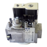
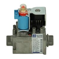
Lists components of the 840 SIGMA control with corresponding numbers.
Lists key technical characteristics and optional features of the control.
Provides a schematic diagram of the gas flow through the control.
Specifies technical data according to European standard EN 126.
Details electrical specifications for automatic shut-off valves.
Graph showing gas flow rate relative to pressure drop for different gas families.
Graphs showing regulated flow based on outlet pressure for different gas groups.
General requirements and verification for installation on appliances.
Provides general recommendations for making mechanical connections.
Step-by-step guide to adjust the outlet pressure using specific screws.
Instructions for checking and adjusting for different gas families.
Guidance on changing gas groups within the same family.
Lists available accessories for the control.
| Brand | Sit |
|---|---|
| Model | 840 SIGMA |
| Category | Industrial Equipment |
| Language | English |