4
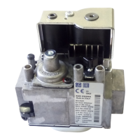
Multifunctional gas control with double safety solenoid and servo-assisted gas outlet pressure regulator. The control is
designed for use in appliances with automatic ignition and flame detection systems, with direct burner ignition or
intermittent pilot. All the adjustments can be made from the top face and it is suitable for all three gas families.
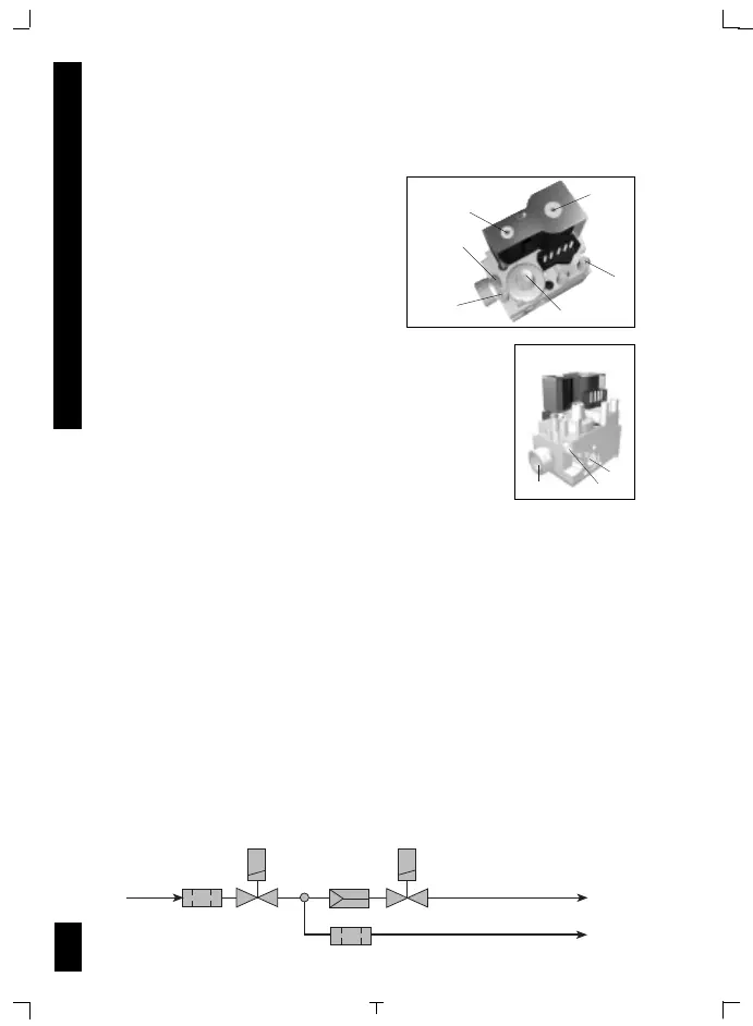
DESCRIPTION
1
On-off solenoid valve EV1
2
On-off solenoid valve EV2
3
Inlet pressure test point
4
Outlet pressure test point
5
Connection for pressure regulator/
combustion chamber compensation
6
Pressure regulator
7
Pilot outlet
8
Main gas outlet
9
Side Outlet
WORKING DIAGRAM
8
7
9
840
840
2
1
5
4
6
3
MAIN FEATURES
ON/OFF solenoid valves: EV1 Class B (on request class A)
EV2 Class J (on request class C)
Servo pressure regulator (PR) class B
Inlet filter
Outlet filter (optional)
Pilot outlet (optional) with filter
Side outlet (optional)
Connection for pressure regulator/combustion chamber compensation
Inlet and outlet pressure test points with “captured” screws
Two mounting holes
Slow opening ignition device (optional)
USE AND INSTALLATION INSTRUCTIONS