REV. 02 8 / 30
CHAPTER 4 - PRODUCT DESCRIPTION
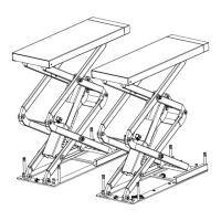
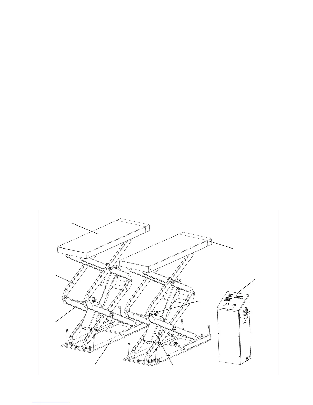
4.1 LIFT DESCRIPTION (Ref. Figure 1)
The flush mounted lift has been designed for the lifting of motor-vehicles for wheel alignment and
maintenance.
The maximum lifting weight is as specified on the serial plate.
All mechanical frames, such as platforms, extensions, base frames and arms have been built in steel
plate to make the frame stiff and strong while keeping a low weight
The electro hydraulic operation is described in detail in chapter 8.
This chapter describes the lift’s principal elements, allowing the user to be familiar with the machine.
As shown in figure 1, the lift is composed of two platforms (1) each equipped with a telescopic
extension (2), anchored to the ground by means of two base frames (3).
Platforms are linked to the base frame by means of a scissors lifting system.
The lifting system of each platform is composed of N.4 arms, two inferior (4) and two superior (5),
and a cylinder (6).
Lifting and lowering motion of the lift is controlled by the push buttons on the control panel (7) placed
next to the lift.
The mechanical safety operating by a pneumatic cylinder (8) is installed under each runway.
Two limit switches are installed in the power unit, one for the safety height and the other one for the
maximum lifting height.
Whenever the lift is to be lowered to the ground, the lift will stop at about 400 mm from the ground at
first, then press the final lowering button to lower the lift completely. A beep sound is heard during the
final travel.
Figure 1 – LIFT
1
2
3
5
4
6
7
8