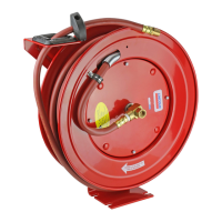
Adjust hose bumper
1 Pull out hose until latch pawl engages.
2 Loosen slotted screws († Fig. 7).
3 Slide bumper to desired position.
4 Tighten screws.
5 Pull hose to disengage latch pawl.
6 Allow hose to retract into reel.
Remove guide arm
1 Pull out hose until latch pawl is engaged.
2 Remove slotted screws holding bumper in
place († Fig. 7).
3 Remove bumper.
4 Allow hose to retract into reel.
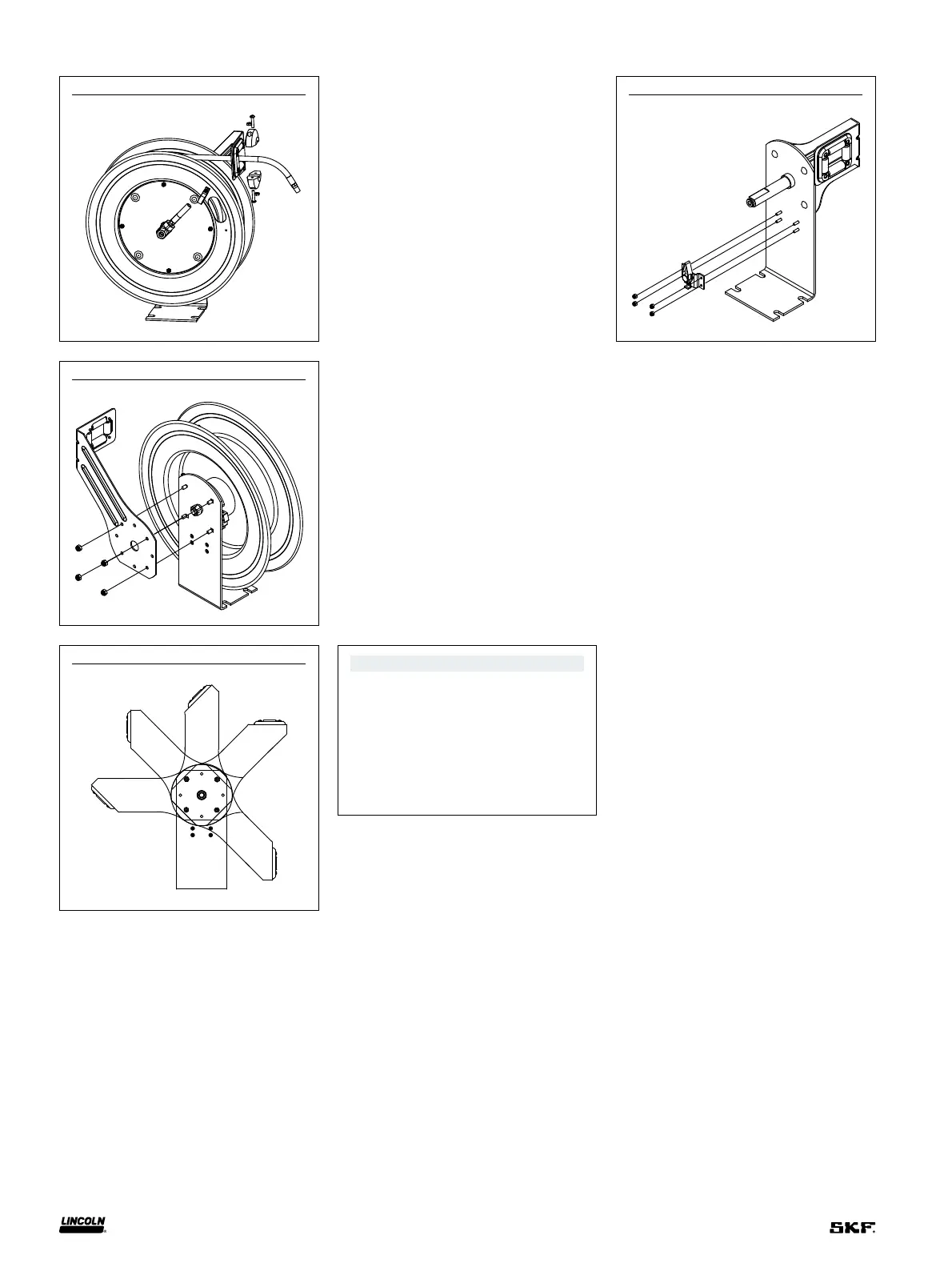
5 Remove nuts holding guide arm on base
(† Fig. 8).
6 Pull guide arm off base.
Fig. 7
Fig. 8
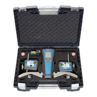
Fig. 9
Fig. 10
NOTE
Recommended guide arm positions
for mounting applications, refer to
Figs. 3, 4 and 5, page 3.
Replace latch pawl
1 Retract hose onto reel until bumper is
against guide rollers and latch pawl is
not engaged.
2 Remove nuts that fasten latch pawl
assembly with socket-head cap screws.
3 Replace latch pawl assembly and
tighten nuts.
Position guide arm
1 Remove guide arm.
2 Position guide arm in one of five positions
(† Fig. 9).
3 Install and tighten four nuts on guide arm.
4 Tighten drive spring by turning spool two
or three revolutions to engage latch pawl.
5 Pull hose through roller opening in
guide arm.
6 Position bumper on hose.
7 Install and tighten screws in bumper.
Refer to Fig. 7.