EasyManua.ls Logo

SKF Lincoln P653S User Manual

SKF Lincoln P653S
56 pages
To Next Page IconTo Next Page
Page #1 background imageLoading...
Page #1 background image
User and maintenance instructions
 V DC or / V AC, - Hz.
Electric operated Centro-Matic
pumps PS
Date of issue March 2018
Form number 404372
Version 2

Table of Contents

Other manuals for SKF Lincoln P653S

Question and Answer IconNeed help?

Do you have a question about the SKF Lincoln P653S and is the answer not in the manual?

SKF Lincoln P653S Specifications

General IconGeneral
ModelP653S
ManufacturerSKF Lincoln
MaterialSteel
Maximum Pressure5500 psi (380 bar)
Temperature Range-4°F to +158°F (-20°C to +70°C)
Voltage120 VAC
GreaseNLGI 000 to NLGI 2
Reservoir Capacity2.2 lb (1 kg)

Summary

Safety

Explanation of Signal Words for Safety

Defines safety signal words like NOTE, CAUTION, WARNING, DANGER.

User's Responsibility

Environmental Protection

Service

Safety Instructions

Appropriate Use

Defines intended applications for the P653S pump.

Misuse

Describes actions considered misuse and their consequences.

Exclusion of Liability

Lists conditions under which manufacturer accepts no liability.

Regulation for Prevention of Accidents

General Safety Instructions

Operation, Maintenance and Repair

Repair

Details authorized personnel for pump repair.

Operation/Maintenance

Covers regular checks and maintenance for pump operation.

Disposal

Instructions for proper disposal of lubricants and parts.

Installation

Installation and Maintenance of Hydraulic Hoses

Lubrication Hose Lines

Guidelines for handling and maintaining lubrication hose lines.

Description

Pump P653S

Details pump specifications, temperature range, and pressure capabilities.

Reservoir Sizes

Lists available reservoir capacities for the pump.

Electrical Connection

Explains electrical connection methods for AC and mobile applications.

Identification Code P653S Pump

Jumper Setting Combinations - Centro-Matic Pumps

Description of Operation

Pump Operation

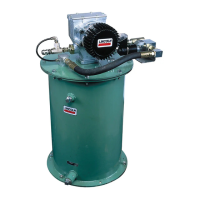
Describes the drive mechanism and components of the pump.

Lube Cycle/Pressurization

Explains the lubrication cycle and pressure build-up process.

Pump Element Operation

Pressure Control/Hold Time/Vent Cycle

Pump with Internal Pressure Switch Only

Describes operation with only an internal pressure switch.

Pump with Internal and External Pressure Switch

Explains operation with both internal and external pressure switches.

Holding Time (H1)

Details the first holding period (H1) for pressure build-up.

Holding Time (H2) – Will Last for 30 Seconds

Describes the second holding period (H2) and its duration.

Holding Time (H3)

Explains the third holding period (H3) and its conditions.

Possible Faults

Lists potential faults (E1, E3) related to pressure control.

Pump with Internal Pressure Transducer Only

Holding Time (H1)

Specifies H1 holding time for internal pressure transducer.

Holding Time (H2) – Will Last for 30 Seconds

Details H2 holding time for internal pressure transducer.

Possible Faults

Lists potential faults (E1, E3) for internal pressure transducer operation.

Pump with Internal and External Pressure Transducer

Holding Time (H1)

Details H1 holding time for combined transducers.

Holding Time (H2) – Will Last for 30 Seconds

Describes H2 holding time for combined transducers.

Holding Time (H3)

Explains H3 holding time for combined transducers.

Possible Faults

Lists potential faults (E1) for combined transducer operation.

Vent Cycle

Fill Reservoir with Grease

Air Expel Procedures for Pumps with Follower

Stirring Paddle

Low-Level Control

Pump with Follower Plate

Pump Without Follower Plate

Grease Reservoir Full of Grease

Grease Reservoir Empty

Keypad and Display

Membrane Keypad

Describes the membrane keypad layout and functions.

Test Display of Membrane Keypad

Operating Mode

Display of a Low-Level Indication

Shows how a low-level condition is displayed.

Ignition Switch Closed (On)

Indicates system status when ignition is closed.

Lubricating Time, Pump is Running

Displays pump status during lubrication.

Malfunctions

Display of Holding Time

Shows display indications for holding times.

Display of Malfunction E1, Failure to Build Pressure at Pump

Displays error E1 for failure to build pressure.

Display of Malfunction E2, Failure to Build Pressure at End of Line

Displays error E2 for failure to build pressure at end of line.

Display of Malfunction E3, Failure to Vent at Pump

Displays error E3 for failure to vent at pump.

Display of Malfunction E4, Failure to Vent at End of Line

Displays error E4 for failure to vent at end of line.

Operator Key to Trigger Additional Lubrication Cycle

Operator Key to Acknowledge Fault

Factory Settings for Parameters

P1

Parameter for setting pause time in hours.

00

Parameter for setting pause time in minutes.

NO

Setting for fault relay output (normally open).

02

Option for fault signaling configuration.

SP

Setting for pump start mode (pause time or lube cycle).

35

Parameter P7 for internal pressure transducer setting.

09

Parameter P8 for external pressure transducer setting.

Acknowledge Fault

To Acknowledge Malfunction

Steps to acknowledge and clear fault indications.

Program Pump

Programming Mode: Pump with Pressure Switch

Guide to programming pumps with pressure switches.

Setting Pause Time (P1 & P2)

How to set pause times P1 (hours) and P2 (minutes).

Programming Alarm Relays (P4)

How to program output signals for alarm relays.

Fault Signaling & Start Mode (P5/P6)

Configuration options for fault signaling and pump start mode.

Program Pump with Pressure Transducer

Complete Programming Steps

Steps to complete the programming process.

Setting Internal Transducer Pressure (P7)

Setting the closing pressure for the internal transducer.

Setting External Transducer Pressure (P8)

Setting the opening pressure for the external transducer.

Review of Pump Parameters

Operating Mode

NO - Both Relay Contacts Are Normally Open

Display example for NO relay configuration.

02 - Option 2 - How F1 and F2 Will Signal a Fault.

Display example for Option 2 fault signaling.

SP - Pump Starts with a Pause Time

Display example for SP start mode.

Indicates That Internal Pressure Transducer Will Close at 3 500 psi (240 bar).

Display indicating internal transducer closing pressure.

Will Only Appear If Pump Has Internal and External Pressure Transducer.

Indicates Software Version.

Termination of Reviewing of Parameters.

Specifications

Electrical Data for DC Pump

Electrical specifications for 24 V DC pumps.

Electrical Data for AC Pump

Electrical specifications for 100-240 V AC pumps.

Common Electrical Data for DC and AC Pumps

Shared electrical data for both pump types.

Rating for Fault Relay Contact:

Specifications for fault relay contacts.

Pump P653S

Specific operating parameters for the P653S pump.

End of Line Pressure Switch Setting

Setting for end-of-line pressure switches.

End of Line Pressure Transducer Setting

Setting for end-of-line pressure transducers.

Maximum Distance Using Shielded Wire for Pressure Transducer*

Max distance for shielded transducer wire.

Operating Temperature Range for DC Pumps

Operating temp range for DC pumps.

Operating Temperature Range for AC Pumps

Operating temp range for AC pumps.

Number of Outlets (see instructions)

Number of outlets on the pump.

Lubricant

Lubricant grade recommendations.

Output

Pump output specifications.

Reservoir Sizes, L

Available reservoir sizes.

Lubricant Line Connection Size

Size of lubricant line connection.

Pump Elements K7

Specifications for pump elements.

Tightening Torques

Torque values for various components.

Weights

Weight information for pump configurations.

Packing (cardboard box)

Packing details.

Attaching Parts

Information on attaching parts.

Operating Instructions

General operating instructions.

Installation

Installation guidelines for hydraulic lines.

Connections for 24 V DC 653 Pump

Connections for 110 - 230 V AC 50/60 Hz 653 Pump

Jumper Settings for 653 Pump PCB

Centro-Matic System Schematic with P653S Pump

NOTE

Important notes regarding vent pressure for proper system operation.

List of Lubricants

NOTE

Caution regarding lubricant compatibility and manufacturer liability.

Proven Lubricants

Lists lubricants tested for pumpability and venting.

Proven Lubricants (continued)

NOTE

Advice on consulting representatives for lubricants with solid additives.

Proven Lubricants (continued)

Lubricants for Food and Beverage Industry

Lubricants approved for food and beverage applications.

Dimensions - P653S: 4 I Reservoir

Dimensions, P653S, 8 I Reservoir

Dimensions, P653S, 15 I Reservoir

Dimensions, P653S, 20 I Reservoir

Refill and Maintenance

Pump Cleaning

Recommended methods for cleaning the pump.

Pump with Follower Plate

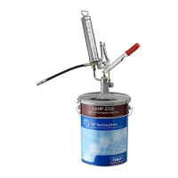
Instructions for refilling and maintaining pumps with a follower plate.

Pump Without Follower Plate

Instructions for refilling and maintaining pumps without a follower plate.

Pump Mounting Template

Troubleshooting

Mode of Failure

Lists various modes of failure and their symptoms.

Pump Without Follower - Exploded View

Pump With Follower - Exploded View

P653S Pump With Follower Parts List

P653S Pump Without Follower Parts List

EC Declaration of Incorporation

Warranty

Related product manuals