EasyManuals Logo

SKF MAXILUBE MAX 230-IF105 Series User Manual

SKF MAXILUBE MAX 230-IF105 Series
47 pages
To Next Page IconTo Next Page
To Previous Page IconTo Previous Page
Page #41 background imageLoading...
Page #41 background image
41
14.2 Connections
14.2.1 SKF Maxilube changeover valve unit
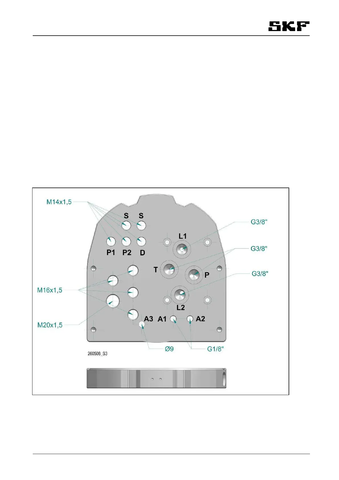
Inputs
A1: pressure air, ø8 mm push in connector (G1/8)
D: low level switch, connector M12
P1, P2: pressure control, 2 pcs, connector M12
power input, M20x1,5 cable gland
Outputs
L1, L2: lubricant, 1 or 2 pcs (line 1 out, line 2 out), DIN 2353 connector for ø12 or 1/2" pipe (G1/4)
S: pumping centre 2 or shut-off valve, 2 pcs, connector M12
A3: exhaust pressure air Ø9 lead-in for pipe Ø6
Cable channels in the bottom plate
M16x1,5 cable gland, 4 pcs, for 410 mm cable diameters
Figure 6: Connections of Maxilube

Table of Contents

Other manuals for SKF MAXILUBE MAX 230-IF105 Series

Questions and Answers:

Question and Answer IconNeed help?

Do you have a question about the SKF MAXILUBE MAX 230-IF105 Series and is the answer not in the manual?

SKF MAXILUBE MAX 230-IF105 Series Specifications

General IconGeneral
BrandSKF
ModelMAXILUBE MAX 230-IF105 Series
CategoryWater Pump
LanguageEnglish

Related product manuals