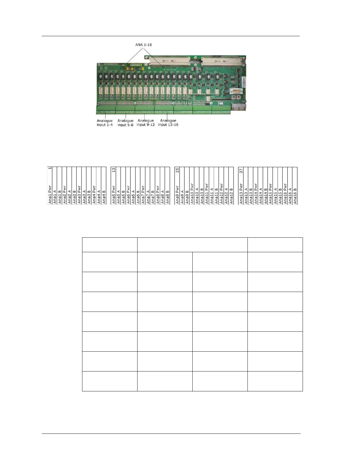
EasyManuals Logo
Home>SKF>Control Systems>Multilog IMx-S 16

SKF Multilog IMx-S 16 User Manual

SKF Multilog IMx-S 16
52 pages
To Next Page IconTo Next Page
To Previous Page IconTo Previous Page
Page #16 background imageLoading...
Page #16 background image
Unit Configuration
Analogue Inputs
3 - 2 SKF Multilog On-Line System IMx-S
User Manual Revision S
Figure 3 - 2.
IMx-S I/O Board, Analogue Inputs.
Table 3-2: Analogue terminal list.
The DIP switch settings for connected analogue sensors must be applied according to
the table below.
Table 3-3: DIP switch settings for analogue sensors.
Signal
Terminal
DIP Settings
position: 123456
Standard
accelerometer
(2-wire, IEPE)
N.C.
+ Signal/Pwr
Com.
100110
Voltage source
N.C.
+ Signal
Com.
000000
420 mA source
N.C.
+ Signal
Signal
000001
B-sensor (420 mA
output)
+24 V
Signal
Com.
100101
Eddy current probe
(24 V)
24 V
Signal
Com.
011000
Voltage powered
sensor (max 35 mA)
+24 V
Signal
Com.
100100
420 mA (IMx
powered)
+ Signal
Signal
N.C.
100101
N.C. = Not Connected
DIP switch setting 1 = ON, 0 = OFF

Questions and Answers:

Question and Answer IconNeed help?

Do you have a question about the SKF Multilog IMx-S 16 and is the answer not in the manual?

SKF Multilog IMx-S 16 Specifications

General IconGeneral
BrandSKF
ModelMultilog IMx-S 16
CategoryControl Systems
LanguageEnglish

Related product manuals