Unit Configuration
RS485 Communication
SKF Multilog On-Line System IMx-S 3 - 5
User Manual – Revision S
RS485 Communication
Twisted pair shielded cable shall be used.
Important - Connect the shield only at one end to avoid ground loops.
The cable connection should be according to the following:
Table 3-7: Cable connection.
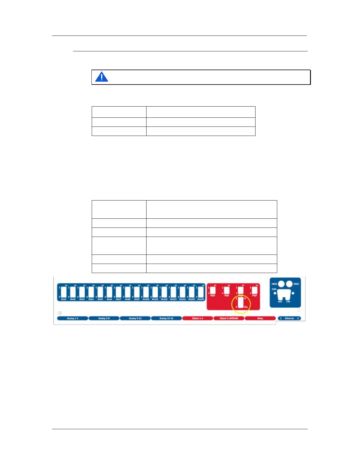
If the IMx-S unit is at the end or beginning of the RS485 Bus, activate the built-in
termination resistor by setting DIP21 according to the table below. DIP21 can be
accessed after the front panel has been taken off. It is located below the Dig3 DIP switch.
➢ On newer systems there is a hole in the front panel for DIP21 (no
need to remove front panel).
Table 3-8: DIP21 functionality.
DIP21 settings
position: 1234
Functionality with I/O board version less than
v1.24 (DIP21-switch with 4 positions)
Termination resistor enabled RS 485
Termination resistor disabled RS 485
DIP21 settings
position: 123456
Functionality with I/O board v1.24 or greater
(DIP21-switch with 6 positions)
Termination resistor enabled
Termination resistor disabled
Figure 3 - 4.
Front Panel with DIP21 Hole (I/O board v1.24 or Greater).
This 2-wire RS485 communication supports Modbus RTU protocol in which the IMx-S can
be configured as a Modbus master or as a Modbus slave device. For more information
regarding RS485/Modbus and the different configurations that are supported, refer to
the appropriate user manual, "Modbus for SKF IMx and @ptitude Observer" o Modbus
for SKF IMx and @ptitude Analyst ad also the appliatio ote Geeal Modus
Protocol Considerations for IMx-Devices" .
 Loading...

