Unit Configuration
Digital Inputs
3 - 4 SKF Multilog On-Line System IMx-S
User Manual – Revision S
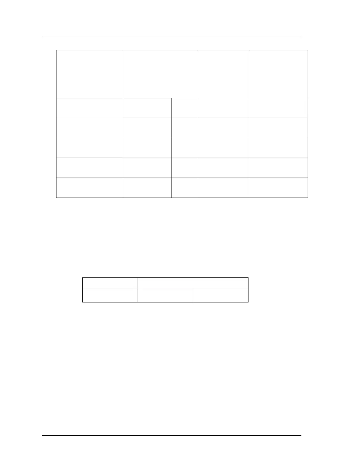
Table 3-5: DIP switch setting for digital sensors.
DIP Settings
position: 1234
(with I/O-board
version less
than v1.24)
DIP Settings
position: 1234
(with I/O board
v1.24 or greater,
with a hole in front
panel for DIP21)
Tacho 2-wire
(24 V internally powered,
max 30 mA)
Tacho 3-wire NPN
(24 V internally powered,
max 30 mA)
Brown (+24 V)
Black (Signal)
Blue (0 V)
Tacho 3-wire PNP
(24 V internally powered,
max 30 mA)
Brown (+24 V)
Black (Signal)
Blue (0 V)
Pulse 12–24 V
(external power)
Pulse TTL
(external power)
N.C. = Not Connected
DIP switch setting 1 = ON, 0 = OFF
DIP position 4 has no effect on the older I/O board (less than V1.24).
Digital inputs 5 to 8 (Dig5 to Dig8) are non-configurable and sensor power is from
external source.
They are only used for externally powered signals with signal level of 12 to 24 V, square
wave signal.
Table 3-6: Digital inputs 5 to 8 terminal list.
Pulse 12–24 V
(external power)
 Loading...

