21
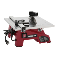
! make sure that the rip fence is locked securely
before sawing
• Auxiliary fence
o
Use the auxiliary fence H when cutting thin workpieces
(18mm or less) close to the blade
- unlock rail lock lever L
- slide the rip fence G close to the blade (position 1)
- ip the auxiliary fence H and click into the highest
position
- adjust the rip fence G to the desired distance with rail
drive knob M
- lock rail lock lever L
• Saw table extension
p
- unlock rail lock lever L
- slide the rip fence G past the edge of the table (use
position 2)
- ip the auxiliary fence H and click into lowest position to
use as workpiece support
- adjust the rip fence G to the desired distance with rail
drive knob M
- lock rail lock lever L
• Lengthways cutting (ripping)
! make sure the rip fence is locked
! when using the rip fence do not use the mitre
gauge
- hold the workpiece with both hands and press it against
the table
a
- use push stick N when the distance between the fence
and the saw blade is less than 150 mm
s
- use a push block (not standard included) when this
distance is less than 50 mm
d
- saw through the workpiece applying a uniform feed
- when cutting long boards or large panels use auxiliary
work supports to support the free end
a
- when the workpiece is warped, place the concave side
down to prevent rocking
- the workpiece must have a straight edge to face
against the rip fence
- when cutting very thin workpieces (5mm or less) an
auxiliary fence facing should be used
f
- clamp a 18mm thick plywood board to the rip fence G
as shown, make sure that it is resting on the table top
• Crossways cutting
- insert the mitre gauge E in one of the slots F in the table
! when beveling (to the left) use the mitre gauge on
the opposite side only
h
c
! when using the mitre gauge do not use the rip
fence
- loosen lock knob AH
g
- rotate the mitre gauge to the desired angle (-60° to 60°)
- tighten lock knob AH
! make sure the mitre gauge is locked
- make some trial cuts and measure if extreme accuracy
is required
- hold the workpiece against the mitre gauge with one
hand and place the other hand on the lock knob to
guide the workpiece slowly forwards
h
- when needed an auxiliary fence can be mounted
j
- for repetitive cutting, a length stop block can be used
k
! do not use the rip fence as length stop
! make sure that the block is positioned well in front
of the saw blade
- foot V can be adjusted as shown to enhance stability
8
c
• Assembly
- assemble the drive knob M with hex key AF
9
- remove table insert D as shown
q
- raise the saw blade to the highest position by rotating
blade wheel S clockwise
- position the riving knife B to the highest position 1
w
- assemble table insert D and lock it in place
q
- assemble the protective guard C as shown
e
a, make
sure that the middle part is parallel to the table top
e
b
- check the protective guard C for proper function;
it should keep in contact with the table top when
changing the saw blade height and bevel settings
- check the protective guard C for proper closing before
each use
! do not operate the saw if the protective guard
does not move freely and close instantly
- assemble the rip fence G as shown
r
- make sure that the lock levers are in released position
• Dust/chip extraction
- mount vacuum cleaner adapter AE as illustrated
t
a
- connect vacuum cleaner
- alternatively, mount dust deector Z to guide the dust
into a bucket
t
b
• Work helpers
y
- some sawing operations will require the use of
additional work helpers
- use push block when working with narrow workpieces
when you need to push close to the saw blade
y
a
- use featherboards for all non-through-cutting
operations where the protective guard cannot be used
y
b
- push block and featherboards may be purchased at
specialist woodworking stores
• Setting bevel angles
u
- loosen bevel lock lever R
- swing the saw to the desired bevel angle
- the saw has end stops at 0° and 45°
- to reach -2 and 47°, press release knob AO to be able
to swing the saw 2° further
u
b
- tighten the bevel lock lever R to secure the bevel setting
• Setting blade height
Set the saw blade approx. 3-6mm higher than the
workpiece
- rotate blade wheel S clockwise to raise the saw blade
- rotate blade wheel S counterclockwise to lower the saw
blade
• Rip fence
i
- the rip fence G has 3 positions
! make sure that the guiding surface is always
facing the saw blade
- use position 1 in combination with the white scale
- use position 2 for maximum rip capacity in combination
with the black scale
! when beveling (to the left) use the rip fence on the
opposite side only (position 1 or 2)
- use position 3 for using the rip fence on the left side of
the blade
- unlock rail lock lever L
- adjust the rip fence G to the desired distance with rail
drive knob M
- lock rail lock lever L


 To Next Page