ELECTRONIC SPARK SYSTEM CHECK
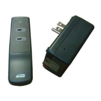
• Slide the 3-position button on the remote receiver to the ON position. The spark electrode should begin sparking to ignite the pilot.
After the pilot ame is lit, the main gas valve should open and the main gas ame should ignite.
• Slide the button to OFF. The main gas ame and pilot ame should both extinguish.
• Slide the button to REMOTE, then press the ON button on the transmitter to change the system to on. The spark electrode should
begin sparking to ignite the pilot. After the pilot is lit, the main gas valve should open and the main gas ame should ignite.
LEARNING TRANSMITTER TO RECEIVER
•
• Each transmitter uses a unique security code. It will be necessary to press the LEARN button on the receiver to accept the trans-
mitter security code upon initial use, if batteries are replaced, or if a replacement transmitter is purchased from your dealer or the
factory. In order for the receiver to accept the transmitter security code, be sure the slide button on the receiver is in the REMOTE
position; the receiver will not LEARN if the slide switch is in the ON or OFF position. The LEARN button in located on the front face
of the receiver; inside the small hole labeled LEARN. Using a small screwdriver or end of a paperclip gently press and release
the black LEARN button inside the hole. When you release the LEARN button the receiver will emit an audible “beep”. After the
receiver emits the beep press ANY transmitter button and release. The receiver will emit several beeps indicating that the transmit-
ter’s code has been accepted into the receiver.
WIRING ELECTRONIC SPARK IGNITIONS
ELECTRONIC MODULE
TR
TH
REMOTE
RECEIVER
neutral wire
24VAC
hot wire
120VAC
110/24VAC
Transformer
The remote control receiver can be connected, in series, to a 24VAC
transformer to the TR (transformer) terminal on the ELECTRONIC
MODULE. Connect the hot wire from the 24VAC transformer to either
of the wire terminals on the remote receiver. Connect another wire be-
tween the other receiver wire terminal and the TH (thermostat) terminal
on the ELECTRONIC MODULE.
WIRING INSTRUCTIONS
A qualied electrician should install the remote control system.
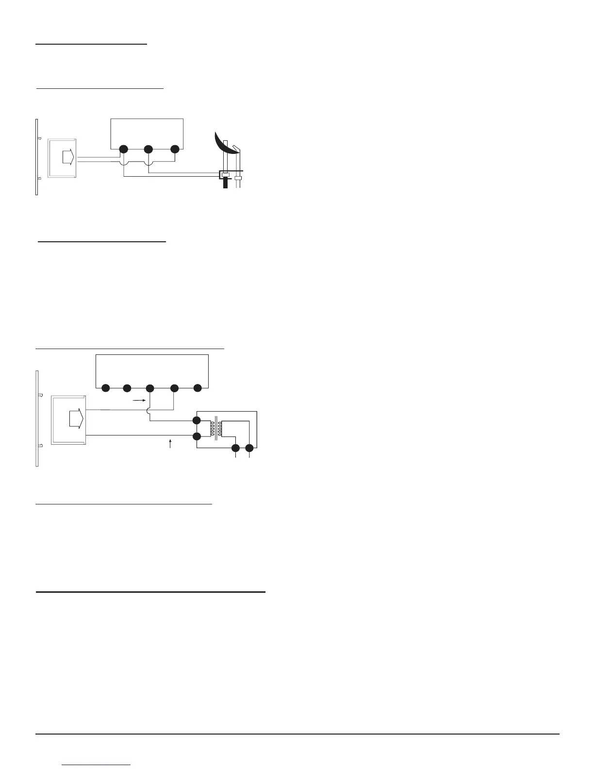
TERMINAL BLOCK
ON MILLIVOLT
GAS VALVES
TH
TP
TP
TH
THERMOPILE/
PILOT LIGHT
REMOTE
RECEIVER
• Connect one wire from the remote receiver to the TH terminal on the gas
valve.
• Connect the other wire from the remote receiver to the TH/TP terminal on
the gas valve.
WIRING MILLIVOLT VALVES
MILLIVOLT SYSTEM CHECK
• Ensure that the pilot ame is lit.
• Slide the 3-position button on the remote receiver to the ON position. The main gas ame (i.e., the re)
should ignite.
• Slide the button to OFF. The main ame should extinguish (the pilot ame will remain on).
• Slide the button to REMOTE, then press the ON button on the transmitter to change the system to on. The main
gas ame should ignite.
Skytech 1001-A
REV. 11-8-16 Page 3