MC_0735
S-link External Switch Interface Installation
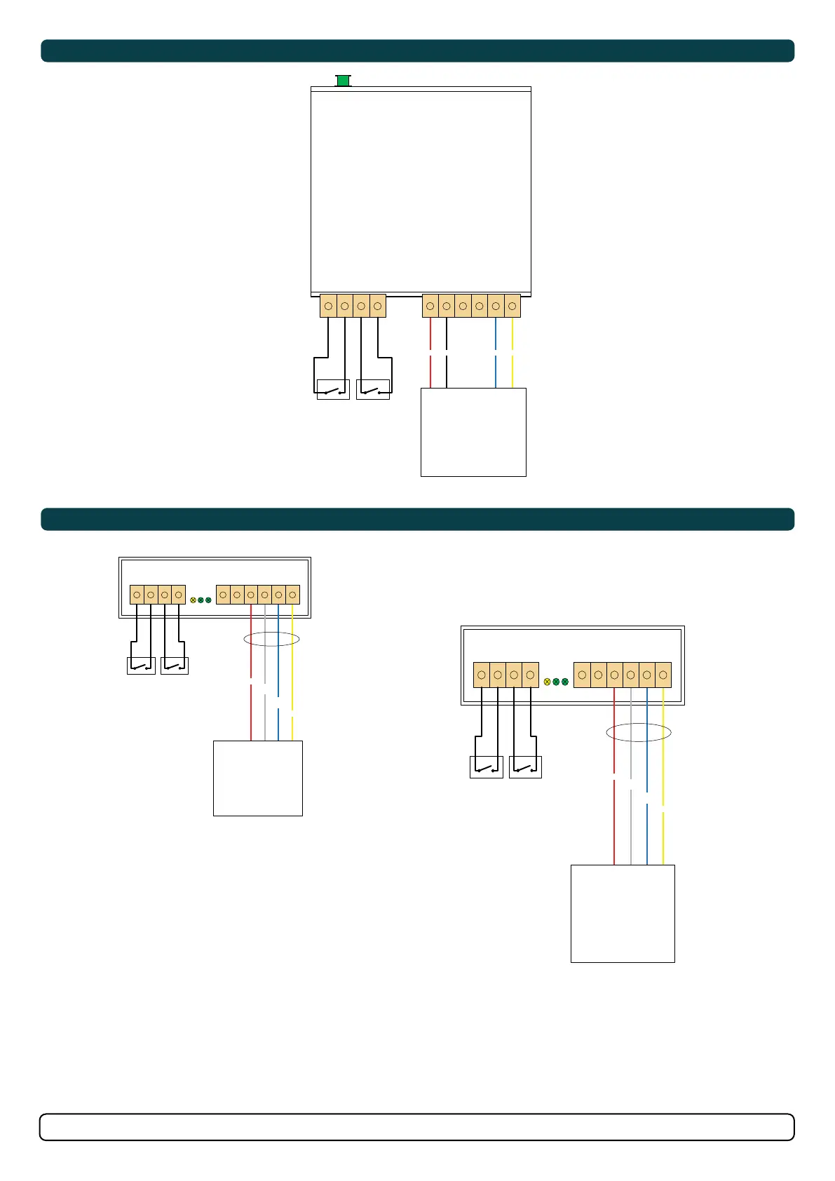
Connect the (foot) switches according to the wiring diagram(s).
1. To connect the optional radio remote, fi rst cut the wires close to the plastic connector on the “bow” connection lead according to Fig. 1. Strip the
wires properly and connect to the 8730 according to the wiring diagram(s). Do the same with the “stern” wires if needed.
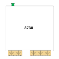
2. Mount the 8730 in a place where it will be protected from direct and condensed water ingress. Use cable ties or other suitable means of
mounting.
3. Plug the S-link Spur cable into the green connector at the rear of interface box. Twist the locking ring on the connector clockwise to secure
connector.