7
2 0 71
4 2024
-
Sleipner Installation Guide
MG_0762
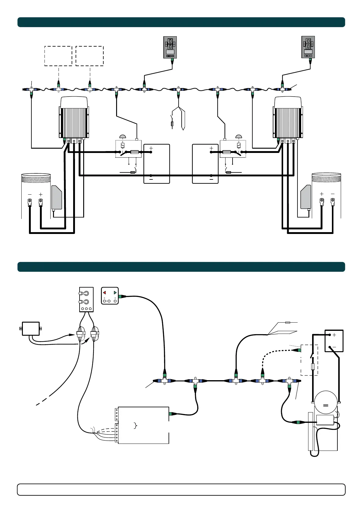
Radio remote
RC10 (optional)
Double Joystick
Panel 8940
Retract panel
This panel must be installed for setup and diagnostics
5-lead Sleipner
control cable
Terminator
120 ohm
8730
black
red
grey
blue
yellow
To Sleipner thruster
(Standard ‘on-off’)
(Bow or Stern)
R
Connect these two wires if
retract is a bow thruster
NB: Common negative for S-link supply and thruster batteries. In this
example all S-link devices must be setup as either ‘stern’ or ‘bow’.
S-link power
supply cable
Terminator
120 ohm
Actuator
Retract Thruster
SR/SRV/SRL
(Stern or Bow)
+ -
M
red
black
5A
+12V/24V
+12V/24V
S-link supply, preferred
from service battery
Battery
S-link automatic version
(optional)
yellow
-
Main Switch
Main Fuse
MG_0761
S-link
Relay
port
Relay
starboard
Thruster Enable
Signal
MG_0328
+12/24V
-
5A
S-link on/off
switch
red
yellow
black
12/24V12/24V
Stern thruster
battery
Bow thruster
battery
Bow thruster
(SEP model)
Stern thruster
(SEP model)
-
black
+
red
B+
-
black
+
red
B+
Fixed multicable 5m
Fixed multicable 5m
5A
+12/24
5A
+12/24
PPC
PPC
Proportional
Power Controller
Proportional
Power Controller
PJC 212
Proportional
joystick
control panel
Bow and stern
Station 1
Automatic Main Switch
8977 12 / 8977 24
or
Manual main switch
w/ANL fuse
Automatic Main Switch
8977 12 / 8977 24
or
Manual main switch
w/ANL fuse
S-link control system
End terminator
End terminator
PJC 212
Observe PPC battery
terminal polarity !
S-link supply
S-link external
switch interface
and remote
(optional)
S-link external
switch interface
and remote
(optional)
Proportional
joystick
control panel
Bow and stern
Station 2
8730
8730
MC_0736
Sample S-link System Setup
MC_0736
Wiring Example: Sleipner Retract Thruster and ‘on-off’ Thruster Combined