PRIOR TO INSTALLATION
Prior to installing the Sloan OPTIMA Series Electronic Hand Dryer,
determine the location where the dryer will be installed. Read the
following paragraph entitled “Installation Precautions” and then refer to
Table 1 and Figure 1 for recommended mounting heights.
Installation Precautions
• Mounting surface should be smooth and flat.
• Mount dryer at least 24 inches (610 mm) away from basins.
• Mount dryer at least 20 inches (508 mm) away from corners.
• Mount multiple hand dryers a minimum of 20 inches (508 mm) apart,
center to center.
• Avoid installing hand dryers in narrow hallways and behind swinging
doors.
Table 1 — Recommended Mounting Height
Users Height
Men 50 Inches (1270 mm)
Women 48 Inches (1219 mm)
Children 44 Inches (1118 mm)
Handicapped 42 Inches (1067 mm)
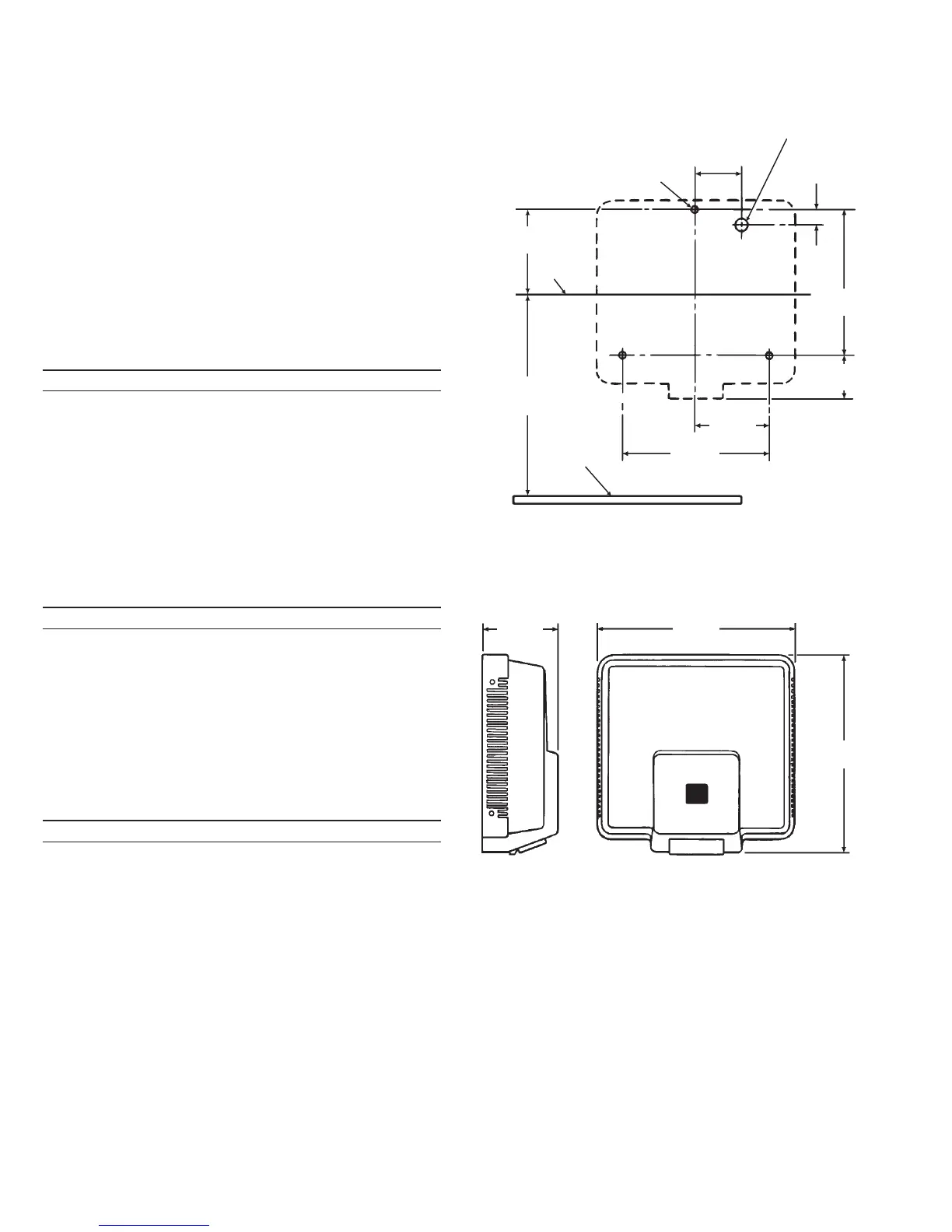
Prepare wall to receive mounting fasteners as shown in Figure 1. Refer
to Table 2 for recommended fasteners.
Note: A mounting template is provided to locate fastener positions.
Table 2 — Recommended Fasteners
Wall Type Fastener Type Qty.
Wall board, metal, hollow tile 1/4" Toggle Bolts 3
Stud wall, wood #14 Screws 3
†
Cement, brick, tile #12-14 Anchors 3
†
†
Installation hardware provided by Sloan.
Drill a 7/8" (22 mm) minimum diameter hole in wall for electrical
connection. Install electrical line in the location shown in Figure 1.
Table 3 — Electrical Requirements
Model Voltage Amps Hz Watts
EHD 120 120 VAC 20 50/60 2400
EHD 208/240
‡
208 VAC 9 50/60 1870
EHD 208/240
‡
240 VAC 10 50/60 2400
‡
Type EHD 208/240 can operate on either 208 VAC or 240 VAC per the
requirements listed.
Note: Connect Hand Dryer to a separate 20 amp branch circuit from the
nearestelectricaldistributionpanel. UseNo.14 gaugeor larger wirefrom
electrical distribution panel to Dryer.
Important: ALL ELECTRICAL WIRING SHOULD BE INSTALLED IN
ACCORDANCE WITH NATIONAL/LOCAL CODES AND
REGULATIONS.
ROUGH-IN — Figure 1
MOUNTING
HEIGHT
(SEE TABLE 1)
3/8" (9.5 mm) DIA.
HOLE (3) PLACES
3/4"
(19 mm)
10"
(254 mm)
LEVEL LINE
4-3/8"
(111 mm)
FINISHED
FLOOR
3-1/8"
(79 mm)
7/8" (22 mm) DIA. HOLE
FOR ELECTRICAL
CONNECTION
2-3/4"
(70 mm)
C/L
5-5/16"
(135 mm)
13-3/4"
(349 mm)
13-3/8"
(340 mm)
8-3/4"
(222 mm)
5-1/2"
(140 mm)
USE MOUNTING TEMPLATE PROVIDED
2
 Loading...