5 Mounting
SMA Solar Technology AG
Installation Manual SBxx-1SP-US-41-IA-xx-10 25
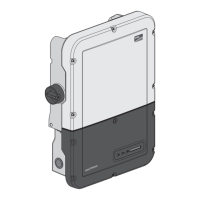
Dimensions for mounting:
126.75
(4.99)
126.75
(4.99)
153
(6.02)
153
(6.02)
1 579.2
(7.06)
179.25
(7.06)
203
(7.99)
203
(7.99)
535
(21.06)
310
(12.2)
9 x 16
(0,34 x 0,63)
730
(28.74)
Figure 5 : Position of the anchoring points(Dimensions in mm (in))
Recommended Clearances:
To guarantee optimal operation and adequate heat dissipation for the inverter as well as a good
connection quality when using the SMACellularLTEModemKit, the following requirements for
clearances should be observed. This will prevent the inverter power output from being reduced due
to excessive temperatures. However, smaller clearances are permitted without causing any risk.
ENGLISH
 Loading...