4 Product Overview
SMA Solar Technology AG
Operating manual STP15-25TL-30-BE-en-17 15
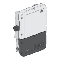
Position Designation
F Display (optional)
The display shows the current operating data and events or errors (see
Section10.1 "Event Messages", page55).
G Lower enclosure lid
H Upper enclosure lid
I DC Load-Break Switch
The inverter is equipped with a DC load-break switch. If the DC load-
break switch is set to the position I, it establishes a conductive connection
between the PV array and the inverter. Setting the DC load-break switch
to the O position interrupts the DC electric circuit and completely discon-
nects the PV array from the inverter. Disconnection takes place at all
poles.
4.2 Symbols on the Product
Symbol Explanation
Beware of a danger zone
This symbol indicates that the product must be additionally grounded if addi-
tional grounding or equipotential bonding is required at the installation site.
Beware of electrical voltage
The product operates at high voltages.
Beware of hot surface
The product can get hot during operation.
Danger to life due to high voltages in the inverter; observe a waiting time of 5
minutes.
High voltages that can cause lethal electric shocks are present in the live com-
ponents of the inverter.
Prior to performing any work on the inverter, disconnect it from all voltage
sources as described in this document.
Observe the documentation
Observe all documentation supplied with the product.
Inverter
Together with the green LED, this symbol indicates the operating state of the in-
verter.

 Loading...